
Instructions / Assembly


5 HAMPTONBAY.com
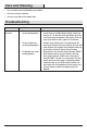
Please contact 1-844-760-3644 for further assistance.
Installation
1
Verifying the transformer
power rating
Power must be supplied from a 16 volt AC, 10 or 15 watt
transformer.
WARNING: This doorbell requires a low voltage electrical
connection. Do not connect directly to 120V AC.
2
Removing the existing doorbell
Ƒ Remove the cover from the existing doorbell
and label all wires with masking tape before
disconnecting:
Ƒ “F” - Front door push button wire
Ƒ “T” - Transformer wire
Ƒ “R” - Rear door push button wire (if
applicable)
Ƒ Disconnect all wires from existing doorbell and
remove doorbell from mounting surface.
FRONT
REA
R
TRANS
R
T
F
3
Mounting the doorbell base
Ƒ Route the wires through the wire entrance hole
in the doorbell base (B).
Ƒ Using the “UP” arrow indicator, place the
doorbell base (B) against the wall and mark
the two screw hole locations.
Ƒ Drill two 7/32 in. pilot holes and insert wall
anchors (BB).
Ƒ Attach the doorbell base (B) to the mounting
surface using the two screws (AA) and tighten
securely.
FR
O
NT
REA
R
TR
AN
S
UP
UP
4
Wiring the doorbell
Ƒ Connect the doorbell wires to the doorbell
base (A):
Ƒ Wire “F” to screw terminal “FRONT”
Ƒ Wire “T” to screw terminal “TRANS”
Ƒ Wire “R” to screw terminal “REAR”
Ƒ Press the doorbell cover (A) onto the doorbell
base (B).
NOTE: To remove doorbell cover (A) after doorbell
base(B) is mounted, rmly grasp doorbell cover (A) and
pull.
NOTE: Push button(s) wired to the screw terminal
marked “FRONT” will play the “Ding-Dong” sound. Push
button(s) wired to the screw terminal marked “REAR” will
play the “Ding” sound.
FRO
NT
REA
R
TR
AN
S
UP
B
AA
B