
Installation guide


8
Parker Hannifin Corporation
Hydraulic Valve Division
Elyria, Ohio 44035 USA
Bulletin 2583-M1/USA
Proportional Directional Control Valves
Series D1FX, 30 Design
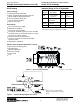
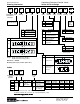
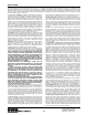
CMD TP2 FLOW LED TP1
Adj Cmd Spool
+10V -10V P Ô A Red -10V
-10V +10V P Ô B Grn +10V
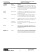
Diagnostic Chart
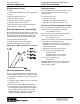
Functional Description (Versions DJ & DK)
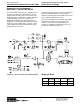
Figure 10 — Version DJ Functional Block Diagram
Standard Driver with Deadband
Eliminators — Versions DJ and DK
The standard D1FX valve may not, depending on the
load, be electrically symmetrical about the no-flow
condition. Occasionally, (such as when using a PLC
generated signal) it is desirable to equalize the signal
needed for similar flow from P to A and P to B.
Deadband or minimum threshold adjustments are
designed to make the D1FX electrically symmetrical
about the no-flow condition.This is a means of more
easily hydraulically nulling and reducing the no-flow
deadband at the same time.
Should this valve be used in a closed loop positioning
system, deadband adjustments are an effective
method of achieving higher repeatability and accuracy
with a relatively low position loop gain.
This valve is available in both a 24 VDC and 12 VDC
nominal power supply. It has the option of either
voltage or current command signal. Reference
voltages are available on the MS connector for the
command or feedback potentiometer.