65B ➤Owner’s/Installation Guide
limited lifetime consumer warranty Directed Electronics, Inc. (hereinafter "Directed") promises to the original purchaser to repair or replace with a comparable reconditioned Directed DIY remote start unit if this Directed DIY remote start unit (hereinafter "Unit"), excluding without limitation, any remote transmitters or associated accessories, proves defective in materials or workmanship under normal use for the life of the vehicle which the Unit is originally installed.
OR IN CONNECTION WITH THE INSTALLATION, USE, IMPROPER USE, OR INABILITY TO USE, THE PRODUCT, EVEN IF THE PARTY HAS BEEN ADVISED OF THE POSSIBILITY OF SUCH DAMAGES. SOME STATES DO NOT ALLOW THE EXCLUSION OF LIMITATION OF INCIDENTAL OR CONSEQUENTIAL DAMAGES, SO THE ABOVE LIMITATIONS OR EXCLUSION MAY NOT APPLY TO YOU. THE CONSUMER AGREES AND CONSENTS THAT ALL DISPUTES BETWEEN THE CONSUMER AND DIRECTED SHALL BE RESOLVED IN ACCORDANCE WITH CALIFORNIA LAWS IN SAN DIEGO COUNTY, CALIFORNIA.
table of contents limited lifetime consumer warranty . . . . . . . . . . . . . . . . . . . . . . . . . . . . . . . . . . . . . . . . i what is included . . . . . . . . . . . . . . . . . . . . . . . . . . . . . . . . . . . . . . . . . . . . . . . . . . . . . . 3 installation tools . . . . . . . . . . . . . . . . . . . . . . . . . . . . . . . . . . . . . . . . . . . . . . . . . . . . . . 3 important information . . . . . . . . . . . . . . . . . . . . . . . . . . . . . . . . . . . . . . . . . . . . . . . . .
2 © 2004 Directed Electronics, Inc.
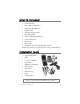
what is included Control Module ➤ One 4-Button Transmitter ➤ 8-Pin Main H/1 Harness ➤ 6-Relay Wires ➤ Shutdown Toggle Switch ➤ Hood Pin Switch ➤ 10 feet of Black Electrical Tape ➤ 6 Six inch Zip Ties ➤ LED Tester ➤ Razor Knife ➤ CDROM—Do-It-Yourself Installation Video Additional parts may be required (such as relays or immobilizer).
important information Congratulations on the purchase of your remote start system. This system will allow convenient remote start of your vehicle. Properly installed, this system will provide years of trouble-free operation. Please take the time to carefully read this User’s Guide in its entirety and watch the Do-It-Yourself Installation Video (CDROM) prior to installing your system. You can print additional or replacement copies of this manual by accessing the Directed web site at www.boasecurity.com.
➜ fcc/id notice This device complies with Part 15 of FCC rules. Operation is subject to the following conditions: (1) This device may not cause harmful interference, and (2) This device must accept any interference received, including interference that may cause undesirable operation. Changes or modifications not expressly approved by the party responsible for compliance could void the user's authority to operate this device.
transmitters to assure that the system does not unintentionally remote start the vehicle. 4. THE USER MUST INSTALL A CARBON MONOXIDE DETECTOR IN OR ABOUT THE LIVING AREA ADJACENT TO THE VEHICLE. ALL DOORS LEADING FROM ADJACENT LIVING AREAS TO THE ENCLOSED OR PARTIALLY ENCLOSED VEHICLE STORAGE AREA MUST AT ALL TIMES REMAIN CLOSED. ➤ Use of this product in a manner contrary to its intended mode of operation may result in property damage, personal injury, or death.
start module must be removed or properly reinstalled so that the vehicle does not start in gear. OPERATION OF THE REMOTE START MODULE IF THE VEHICLE STARTS IN GEAR IS CONTRARY TO ITS INTENDED MODE OF OPERATION. OPERATING THE REMOTE START SYSTEM UNDER THESE CONDI TIONS MAY RESULT IN PROPERTY DAMAGE OR PERSONAL INJURY. IMMEDIATELY CEASE THE USE OF THE UNIT AND REPAIR OR DISCONNECT THE INSTALLED REMOTE START MODULE. DIRECTED WILL NOT BE HELD RESPONSIBLE OR PAY FOR INSTALLATION OR REINSTALLATION COSTS.
primary harness (H/1), 8-pin connector H1/1 BLUE H1/2 VIOLET/WHITE H1/3 BROWN H1/4 GRAY H1/5 BLACK H1/6 WHITE/BLUE H1/7 LT.
using LED test probe note: Do not use this test probe on computerized equipment as damage can result. To use the LED test probe: 1. Remove the protective cover off the probe tip. Save the protective cover for reinstallation on the probe tip when the LED tester is not being used. 2. Connect the Black clip to a good chassis ground. 3. Connect the Red clip to a good +12V source. Both the Red and Green LEDs should be illuminated dimly. 4.
installation Be sure to read this section thoroughly and view the Do-ItYourself Installation CDROM video in its entirety before starting the installation. Pay special attention to all warnings to prevent personal injury or damage to your vehicle. www.boasecurity.com) to Visit our 24-hour technical Web site (w get a vehicle-specific wiring guide prior to starting this installation.
➜ step 1 Ground Wire The BLACK (H1/5) wire on the main 8-pin harness is ground. This wire should be connected to a clean, paint-free area of metal in the drivers kick panel area. First strip back a ¾-inch section of the insulation off the BLACK wire and crimp a ring terminal (not provided) to that wire. Locate a clean, paint-free metal surface in the drivers kick panel. Using a self-tapping screw, drill the screw with the ring terminal to the metal area.
➜ step 2 Constant Power and Ignition wires Almost all power and ignition wires can be found behind the key cylinder under the lower drivers side dash panel. Using the appropriate hand tools, remove the lower dash panel using care not to break any parts. If the panel does not come off easily check for any additional screws you may have missed. Once the lower dash panel has been removed, locate the ignition harness at the back of the key cylinder. This is usually a group of thicker wires.
warning! Before making any connection to constant battery power make sure that the two green 30 amp fuses are removed from the fuse holders on the two thick red wires. Failure to do so may cause fire or shorting of sensitive electrical components. Once the constant power wire (or wires) has been identified, solder the two thick RED wires from the control module to it and cover the connection with electrical tape to ensure a safe connection.
If the vehicle requires more than one ignition as per the Web site information follow the same test procedure and solder the thick PINK/WHITE (F) relay wire to it and be sure to wrap the connection with electrical tape. If your vehicle requires more than two ignitions, contact BOA Technical Support. ➜ step 3 Accessory and Starter wires The starter and accessory wires will be located in the same harness as the ignition and constant power.
Now that the accessories have been located, find the wire suspected to be the starter wire according to the web information on your vehicle. Place the red lead of your LED tester on the wire. With the key in the off position the LED tester should be extinguished in all key positions except the crank position. In the crank position your LED tester should illuminate, and will extinguish when the starter disengages.
➜ step 4 Safety Shutdown Wires important! These wires are meant to protect the vehicle and anyone near the vehicle. They must be connected appropriately to prevent damage to the vehicle and possible bodily injury. Failure to properly install these wires may cause the vehicle to lunge if remote started while in gear. With all ignition wires properly connected, find the appropriate safety shutdown wires. These are the brake wire and hood pin wires. First locate the factory brake wire using your LED tester.
Installing the hood pin switch requires drilling a ¼-inch hole in the metal lip under the hood. Choose a location that will allow the pin switch to be depressed when the hood is closed. The pin switch has a spade connector on the bottom for the wire connection. Place the wire with the spade connector onto the pin switch and run the wire into the vehicle’s passenger compartment through a factory rubber grommet.
temporarily (i.e., for service on the vehicle or when parking in an enclosed area). This switch is to be mounted in an easily accessible location in the passenger compartment. Connect the toggle switch as shown below. HOOD PIN SWITCH OPEN WHEN HOOD IS CLOSED TO GRAY (H1/5) WIRE ON CONTROL MODULE HOOD PIN SWITCH CONNECTOR BYPASS TOGGLE SWITCH BYPASSED WHEN CLOSED ➜ step 5 Parking light flash (optional) There are several different types of parking light circuits.
Using the web information on the vehicle, locate the suspected wire and place the red lead of the LED tester to a constant (+)12 volt source and secure it. Probe the suspected wire. With the switch in the off position the LED tester should be extinguished. While watching the LED tester, turn the switch to the parking light position. The LED tester should illuminate green. While testing the suspected wire, run the dash dimmer light control up and down — the voltage should NOT vary (LED tester illumination).
➜ step 6 Engine monitoring (voltage—default setting) During remote start the system will need to know if the engine is running. The module does this by monitoring the voltage of the vehicle’s electrical system (or the tachometer-see next topic). When the vehicle is not running the electrical system is approximately 12 volts. The system detects the engine running when the voltage equals or exceeds 13.5 volts.
Engine monitoring (tachometer—optional) warning! In the following procedure do not wear loose clothing that could get entangled in rotating engine components. Ensure that your hands and arms are well clear of these rotating components when working in the engine compartment. Lastly, ensure that all wires and tools are clear of falling into or entanglement with these rotating components. note! In the following procedure do NOT use the LED tester.
hood pin wire and pull the wire through the grommet taking extra care to keep it away from any moving parts or anything that will generate extreme heat. Once the wire is run into the engine compartment, strip a small portion of insulation off the tachometer wire and solder it to the VIOLET/WHITE wire and wrap the connection with electrical tape. Pull on the wire to ensure a good connection. note! For the programming of the tachometer, refer to the Control Module Programming discussion.
it. Probe the suspect wire with the LED tester. While probing the wire, place the key in the drivers door cylinder. Turn it to the unlock position and hold it when testing for the disarm wire. The LED tester should illuminate and will extinguish when the key is released. When the correct wire has been found, strip a small portion of insulation off this wire and solder the small LIGHT GREEN/BLACK (H1/7) wire to this wire. Wrap the connection with electrical tape.
dealer. The majority of transponder-based immobilizer systems can be bypassed using the 555U/556U immobilizer bypass module available at your local retail dealer. This BLUE wire (H1/1) of the primary harness supplies a 200mA output as soon as the control module begins the remote start process. This wire can be used to activate an immobilizer bypass unit. To determine what bypass module your vehicle requires, check your web vehicle information sheet. ➜ step 9 The system comes with one transmitter.
2. Program. After 5-seconds, press and hold the PROG button on the transmitter, until—(see step 3). ARM DISARM 3. Parking Lights Flash. The parking lights will flash twice to acknowledge programming of this transmitter. START STOP note: A second transmitter can only be added to the system immediately after programming the first transmitter. To add a second transmitter (within 5-seconds of the first transmitter parking light flash learn acknowledgment): 1. Program.
transmitter functions The receiver uses a computer-based learn routine to learn the transmitter buttons. ➜ standard configuration PROG ARM PROG PROG DISARM ARM ARM PROG DISARM DISARM ARM Button START DISARM START button Press theSTOP START STOP PROG START Button STOP ARM Press the STOP button DISARM twice to remote start the vehicle. PROG once to remote stop the vehicle. ARM DISARM Button This button START engages timer mode.
Control Module Programming Depending on the vehicle, use the following data with the instructions to program your system. These wire loops are found PROG at the side of the control module. ARM Diesel Mode (BLDISARM UE) - Cut this loop if you have a diesel vehicle. When cut the remote start will start the engine about 30 seconds after pressing the START button twice. STOP Uncut – Gas Mode Cut – Diesel Mode Voltage Mode/Tachometer Mode - Default is voltage mode.
using your system ➜ warning! safety first The following safety warnings must be observed at all times: ■ When properly installed, this system can start the vehicle via a command signal from the remote control transmitter. Therefore, never operate the system in an enclosed area or partially enclosed area without ventilation (such as a garage).
feature of the vehicle periodically checked, wherein the vehicle must not remotely start while the car is in gear. This testing should be performed by an authorized Directed Electronics, Inc. dealer in accordance with the Safety Check outlined in the product installation guide. If the vehicle starts in gear, cease remote start operation immediately and consult with the authorized Directed Electronics, Inc.dealer to fix the problem.
➜ remote start This feature allows you to remotely start your vehicle. This makes it possible to warm up the engine, as well as adjust the interior temperature of the vehicle with the climate control system. If interior heating or cooling is desired, the climate controls must be preset, and the fan blower must be set to the desired level prior to remote starting the vehicle.
PROG ARM ■ TheDISARM shutdown toggle switch is put into the ON position. ■ The pre-programmed run time has elapsed (12-minutes). ■ The STOP button is pressed. ■ The tachometer is either too high or low. ■ The battery voltage is too low. START ➜ timer mode This feature allows you to remotely start and run your vehicle for 12-minutes every 3 hours (for a maximum of 6 starts for cold weather conditions).
3. The vehicle will start every 3 hours, it will run for a period of 12-minutes or until a shutdown input is triggered. Remote start timer mode is cancelled by: ■ Activation of the ignition (turning the ignition key On) ■ The car has started 6 times. ■ The brake pedal is pressed. ■ The hood isDISARM opened. ■ The shutdown toggle switch is put into the ON position.
PROG ARM DISARM 3. Do not step on the brake. 4. Press the START button twice. The parking lights will flash STOP twice to confirm pit stop mode. 5. Turn the key off and remove the key. 6. Exit and lock the vehicle. Use the following procedure to exit Pit Stop Mode: 1. Enter the vehicle. 2. Place the key into the on (not the crank or start) position. 3. Step on the brake (this causes the system to exit Pit Stop Mode).
system expansion items The following item can be added to the system: ➤ Starter Kill ➤ Window Automation ➤ Valet® Remote Start troubleshooting ➤ The ignition comes on, but the starter will not crank. Does it start with the key in the ignition? If so, does the vehicle have an engine immobilizer? Will it start with the brake pedal depressed? (Make sure to disconnect the brake shutdown when performing this test.) If so, it may have a brake/starter interlock.
Has the tach wire been learned? See the Tach Learning section of this guide. Is the tach wire receiving the correct information? Either the wrong tach wire has been used, or a bad connection exists. ➤ The climate control system does not work while the unit is operating the vehicle. Either the wrong accessory wire is being energized or more than one ignition or accessory wire must be energized in order to operate the climate control system. ➤ The remote start will not activate.
starter side wire of the vehicle. 4. Does the vehicle have an immobilizer? Some immobilizer systems will not allow the vehicle to crank if active. 5. Check connections. The two red heavy gauge input wires should have solid connections. "T-taps", or "scotch locks" are not recommended for any high current heavy gauge wiring. Also, if the vehicle has more than one 12-volt input wire, then connect one red wire to each. ➤ The vehicle starts, but immediately dies.
© 2004 Directed Electronics, Inc.
notes _________________________________________________ _________________________________________________ _________________________________________________ _________________________________________________ _________________________________________________ _________________________________________________ _________________________________________________ _________________________________________________ _________________________________________________ _________________________________________________ ______
PROG ✂ ARM PROG DISARM ARM QUICK REFERENCE GUIDE: ✂ Cut along dotted line and fold for a quick and easy reference to keep in your purse or wallet. To remoDISARM te start using your remote ■ Press START twice within three seconds. The parking lights will flash once to confirm. STOP START To remote stopPROG using your remote ■ Press STOP ARMonce. The parking lights will flash once to confirm. To use timer DISARM mode ■ Press the button twice within 3 seconds.
The company behind this system is Directed Electronics, Inc. Since its inception, Directed Electronics has had one purpose, to provide consumers with the finest vehicle security and car stereo products and accessories available. The recipient of nearly 100 patents and Innovations Awards in the field of advanced electronic technology, DIRECTED is ISO 9001 registered. Quality Directed Electronics products are sold and serviced throughout North America and around the world.