
Installation guide

© 2001 Directed Electronics, Inc. Vista, CA 17
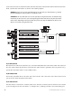
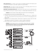
SINGLE-RESISTOR TYPE: If one resistor is used in the door lock switch/key cylinder, the wire will pulse ground
in one direction and resistance to ground when operated in the opposite direction.
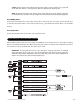
TWO-RESISTOR TYPE: If two resistors are used in the factory door lock switch/key cylinder, the door lock
switch/key cylinder will read resistance to ground in both directions.
DETERMINING THE PROPER RESISTOR VALUES: To determine the resistor values, the door lock switch/key cylinder
must be isolated from the factory door lock system. For testing, use a calibrated digital multimeter that is set to ohms.
IMPORTANT! To ensure an accurate resistance reading, do not touch the resistor or leads during testing.
1. Cut the output wire from the door lock switch/key cylinder in half.
2. Test with the meter from the switch side of the cut door lock switch/key cylinder wire to a reliable ground
source. Some good ground references are the ground input source to the door lock switch/key cylinder or the
battery ground.
3. Operate the door lock switch/key cylinder in both directions to determine the resistor values. If the multi-
meter displays zero resistance in one direction, no resistor is needed for that direction.
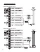
4. Once the resistor value(s) is determined, refer to the wiring diagram for proper wiring.
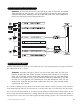
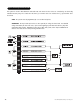
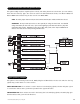
IMPORTANT! The H2/A and H2/B wires are not required for wiring the door locks. For detailed
wiring instructions for these two wires, refer to the beginning of the Door Lock Harness (H2) Wire
Connection Guide section. Depending on the type of door lock system, there may be additional H2
harness wires that are not used for wiring the door locks.