® Model 552T Installation Guide ® 2001 Directed Electronics, Inc.
table of contents Wiring Quick Reference Guide . . . Warning! Safety First . . . . . . . . . Installation Points to Remember . Deciding On Component Locations Control Module. . . . . . . . . . . . Valet®/Program Switch . . . . . . Status LED . . . . . . . . . . . . . . Optional Starter Kill Relay . . . . . . . . . . . . . . . . . . . . . . . . . . . . . . . . . . . . . . . . . . . . . . . . . . . . . . . . . . . . . . . . . . . . . . . . . . . . 3 4 5 6 6 6 7 7 Finding The Wires You Need. . . . .
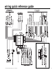
wiring quick reference guide © 2000 Directed Electronics, Inc.
warning! safety first The following safety warnings must be observed at all times: ■ Due to the complexity of this system, installation of this product must only be performed by an authorized DEI dealer. ■ When properly installed, this system can start the vehicle via a command signal from the remote control transmitter. Therefore, never operate the system in an area that does not have adequate ventilation.
installation points to remember before beginning the installation q IMPORTANT! This product is designed for fuel-injected, automatic transmission vehicles only. Installing it in a standard transmission vehicle is dangerous and is contrary to its intended use. ■ Please read this entire installation guide before beginning the installation. The installation of this remote start system requires interfacing with many of the vehicle’s systems.
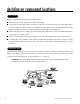
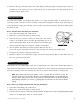
deciding on component locations control module Things to remember when positioning the control module: ■ Never place the control module in the engine compartment! ■ The first thing a thief will do when hot-wiring a vehicle is to remove the driver's side under-dash panel to access the starter and ignition wires. You should therefore avoid placing the control module just behind the driver’s side dash to prevent it from being easily disconnected during a theft attempt.
status LED Things to remember when positioning the status LED: ■ It should be visible from both sides and the rear of the vehicle, if possible. ■ It needs at least 1/2-inch clearance to the rear. ■ It is easiest to use a small removable panel, such as a switch blank or a dash bezel. Remove it before drilling your 9/32-inch hole. ■ Use quick-disconnects near the LED wires if the panel is removable. This lets mechanics or other installers remove the panel without having to cut the wires.
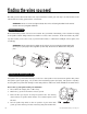
finding the wires you need Now that you have determined where each component will be located, your next step is to find the wires in the vehicle that the security system will be connected to. IMPORTANT! Do not use a 12V test light to locate these wires! All testing described in this manual assumes the use of a digital multimeter. obtaining constant 12V We recommend two possible sources for 12V constant: The (+) terminal of the battery, or the constant 12V supply to the ignition switch.
5. Now turn the key to the start position. The meter display should stay steady, not dropping by more than a few tenths of a volt. If it drops close to or all the way to zero, go back to Step 3. If it stays steady at (+)12V, you have found an ignition wire. finding the starter wire The starter wire provides 12V directly to the starter or to a relay controlling starter. In some vehicles, it is necessary to power a cold start circuit.
4. Turn on the parking lights. If your meter shows (+)12V, turn off the parking lights and make sure it goes back to zero. 5. If it does return to zero, turn the parking lights back on and, using the dash light dimmer control, turn the brightness of the dash lights up and down. If the meter changes more than a volt when using the dimmer, look for another wire. If it stays relatively close to (+)12V, you have found your parking light wire.
4. Probe the wire you suspect of being the tachometer wire with the red probe of the meter. 5. If this is the correct wire the meter will read between 1V and 6V. finding the wait-to-start bulb wire for diesels In diesel vehicles it is necessary to interface with the wire that turns on the WAIT TO START light in the dashboard. This wire illuminates the bulb until the vehicle’s glow plugs are properly heated. When the light goes out the vehicle can be started.
wiring diagrams primary harness (H1) wiring diagram The primary harness supplied with this unit is the standard 12-pin harness used by DEI® security systems. Three wires in the plug are not used. The upgrade from this unit to a security system would simply require unplugging and exchanging control units and connecting the necessary wires to the vehicle.
heavy gauge relay satellite wiring diagram 1 2 3 4 5 6 ______ ______ ______ ______ ______ ______ RED (+) HIGH CURRENT 12V INPUT RED (+) HIGH CURRENT 12V INPUT PINK (+) OUTPUT TO IGNITION CIRCUIT ORANGE (+) OUTPUT TO ACCESSORY CIRCUIT PURPLE (+) OUTPUT TO STARTER CIRCUIT PINK/WHITE (+) OUTPUT TO SECOND IGNITION CIRCUIT auxiliary harness (H2) wiring diagram H2/1 H2/2 ______ ______ GRAY/BLACK (-) WAIT-TO-START INPUT LIGHT GREEN/BLACK (-) FACTORY DISARM/SPECIAL ACCESSORY remote start harness
primary harness (H1) wire connection guide H1/1 ORANGE (-) ground-when-armed output This wire supplies a (-)500 mA ground as long as the system is armed. This output ceases as soon as the system is disarmed. The orange wire may be wired to an optional DEI® 8618 starter kill relay. H1/2 WHITE (+/-) selectable light flash output As shipped, this wire should be connected to the (+) parking light wire.
H1/3 WHITE/BLUE (-) activation input Sending a negative pulse to this wire will initiate the remote start sequence. This wire can be wired to an optional momentary switch to activate the remote start system. H1/4 BLACK /WHITE (-) 200 mA domelight supervision output Connect this wire to the optional domelight supervision relay as shown below: IMPORTANT! This output is only intended to drive a relay.
H1/9 YELLOW (+) ignition output Connect this wire to an optional host alarm or the 86 terminal of an optional starter kill relay. IMPORTANT! If the H1/9 output is not used, care must be taken to prevent this wire from shorting to chassis ground. H1/10 BROWN (-) horn honk output This wire supplies a (-) 200 mA output that can be used to honk the vehicle horn. It outputs a single pulse when locking the doors with the remote, and two pulses when unlocking with the remote.
relay satellite key switch interface wire connection guide All except the red heavy gauge wires leading from the relay satellite are used to energize high current circuits in the vehicle. It is crucial that these connections are made correctly so that they are capable of handling the current demands. For this reason, scotch locks, T-taps and other such connectors should not be used.
auxiliary harness (H2) wire connection guide H2/1 GRAY/BLACK (-) diesel wait-to-start bulb input Connect this wire to the wire in the vehicle that sends the signal to turn on the WAIT-TO-START bulb in the dashboard. In most diesels the wire is negative (ground turns on the bulb) and the GRAY/BLACK can be directly connected to the wire in the vehicle. If the vehicle uses a positive wire (12V to turn on the bulb) a relay must be used to change the polarity.
H2/2 LIGHT GREEN/BLACK (-) auxiliary output This wire sends a negative pulse every time the remote start is activated. This can be used to pulse the disarm wire of the vehicle's factory anti-theft device. Use a relay to send a (-) or (+) pulse to the disarm wire as shown in the diagrams below. This wire can also be used as a special accessory output. (See Feature Descriptions section of this guide.
H3/3 GRAY (-) hood pinswitch input This wire MUST be connected to hood pinswitch. This input will disable or shut down the remote start when the hood is opened. H3/4 BROWN (+) brake switch input This wire MUST be connected to the vehicle's brake light wire. This is the wire that shows (+) 12V when the brake pedal is pressed. The remote start will be disabled or shut down any time the brake pedal is pressed.
neutral safety switch interface Some vehicles combine the column shift mechanism and the mechanical neutral safety switch into one mechanical part. In these vehicles, it is impossible to interface the remote start system before the neutral safety switch. With this type of vehicle, if the vehicle is left in a drive gear and the remote start system is activated, the vehicle will move and may cause damage to persons or property.
Every vehicle built this way requires that the shifter be placed in park to remove the keys from the ignition. As a result, it is possible to use the key-in-ignition sense switch to prevent remote starting if the keys are in the ignition. The diagrams in this section illustrate how to accomplish this. Diagram A applies to all General Motors vehicles at the time of publication of this guide. Diagram B applies to all pre-1996 Dodge Dakota pickup trucks with 2.5 liter motors.
Diagram B - Pre-1996 Dodge Dakota pickups with 2.5 liter motors: 1995 and newer vehicle anti-theft systems (immobilizers) 1995 and newer vehicle anti-theft systems (immobilizers) require a bypass module. The bypass module allows for easy interfacing, while still maintaining the OEM system’s integrity.
passkey III (PK-3), transponder-based systems The Passkey III system can be found in the following vehicles: ■ ‘97 and newer Park Avenue ■ ‘98 and newer Cadillac ■ ‘99 and newer U vans, Transport, Montana, and Silhouette ■ 2000 and newer Grand Prix, Lesabre, Monte Carlo, Lumina, Bonneville ■ 2001 and newer Aurora, Aztek and Rendezvous Other transponder-based systems include: Acura, BMW, Dodge/Chrysler/Jeep, Ford, Honda, Infinity, Mazda, Mercedes, Mitsubishi, Nissan, Toyota, Volkswagon, and Volvo.
NOTE: When connecting to the VATS wires, it is not important which wire is cut. optional anti-grind relay The optional anti-grind relay will prevent the starter from engaging if the ignition key is accidentally turned to the start position during remote start operation. If the blue H2/1 status output has been programmed for factory security re-arm, use the H2/2 blue/black third ignition output to control the relay.
NOTE: A 1-amp diode (type IN4004) must be installed in line on the H2/1 blue status output (or the H2/2 blue/black third ignition output wire) and the orange (-) ground-when-armed wire of the starter kill relay. Insert diodes as shown in the diagram below. plug-in LED and valet/program switch These plug into the module. The status LED plugs into the small two-pin socket, while the Valet®/Program switch should be plugged into the larger blue two-pin connector. The status LED fits in a 9/32-inch hole.
programmer interface, 3-pin port The black 3-pin port is provided for personal computer programming of the unit. The unit can also be programmed using the Bitwriter (p/n 998T). When using the optional PC Interface module, or hand-held programmer, it is possible to configure any and all of the programmable functions as well as lock the Transmitter/Receiver and System Features Learn Routines so that unauthorized users cannot change the configuration or program transmitters to the unit.
Here is a test: Cut the wire which pulses (+)12V on lock, and then operate the switch to unlock. ■ If all doors unlock, the vehicle uses Type A system. ■ If you lose all door lock operation in both directions, you are operating the master switch in a Type C system. ■ If you lose all door lock operation of one or more doors, but not all motors stop operating, and other doors still work, you have cut a wire leading directly to one or more motors. You must instead find the actual wires leading to the switch.
type B: (-) pulses from the switch to the factory relays This system is common in many Toyota, Nissan, Honda, and Saturn models, as well as Fords with the keyless-entry system (some other Fords also use Type B). The switch will have three wires on it, and one wire will test ground all the time. One wire will pulse (-) when the switch locks the doors, and the other wire will pulse (-) when the switch unlocks the doors. This type of system is difficult to mistake for any other type.
type C: reversing polarity Interfacing with a reversing polarity system requires either two relays or one P/N 451M Door Lock Relay Satellite (not included). It is crucial to identify the proper wires and locate the master switch to interface properly. Locate wires that show voltage on lock and unlock. Cut one of the suspect wires and check operation of the locks from both switches.
type D: aftermarket actuators In order for this system to control one or more aftermarket actuators, a P/N 451M Door Lock Relay Satellite (optional) or two relays (optional) are needed. Vehicles without factory power door locks require the installation of one actuator per door. This requires mounting the door lock actuator inside the door. Other vehicles may only require one actuator installed in the driver's door if all door locks are operated when the driver's lock is used.
type E: mercedes-benz and audi (1985 and newer) These door locks are controlled by an electrically activated vacuum pump. Some Mercedes and Audis use a Type D system. Test by locking doors from the passenger key cylinder. If all the doors lock, the vehicle's door lock system can be controlled with just two relays (optional). The control wire can be found in either kick panel and will show (+)12V when doors are unlocked and (-) ground when doors are locked. To interface, see the diagram below.
type G: positive (+) multiplex This system is most commonly found in Ford, Mazda, Chrysler and GM vehicles. The door lock switch or door key cylinder may contain either one or two resistors. When interfacing with this type of door lock system, two relays or a DEI 451M must be used. single-resistor type If one resistor is used in the door lock switch/key cylinder, the wire will pulse (+)12V in one direction and less than (+)12V when operated in the opposite direction.
type H: negative (-) multiplex The system is most commonly found in Ford, Mazda, Chrysler and GM vehicles. The door lock switch or door key cylinder may contain either one or two resistors. single-resistor type If one resistor is used in the door lock switch/key cylinder, the wire will pulse ground in one direction and resistance to ground when operated in the opposite direction.
programming jumpers light flash (+)/(-) This jumper is used to determine the light flash output polarity. In the (+) position, the on-board relay is enabled and the unit will output (+)12V on the WHITE wire, H1/2. In the (-) position, the on-board relay is disabled. The WHITE wire, H1/2, will supply a 200mA (-) output suitable for driving factory parking light relays. NOTE: For parking light circuits that draw 10 amps or more, the internal jumper must be switched to a (-) light flash output.
transmitter/receiver learn routine The system comes with two transmitters that have been taught to the receiver. The receiver can store up to 4 different transmitter codes in memory. Use the following learn routine to add transmitters to the system or to change button assignments if desired. Using the optional DEI Bitwriter or PC Interface, the learn routine may be locked. Make sure the learn routine is unlocked before programming features.
Channels Four, Five and Six: To configure the system's remote transmitters for Separate Button Configuration, Channels 4 through 6 are used to assign the arm, disarm, and panic functions to separate buttons on an optional four-button transmitter. Teaching a button to Channel Four erases all information about that remote from memory. Any auxiliary functions that are desired will have to be reprogrammed.
transmitter configurations The transmitters can be programmed with the separate or single button arm/disarm configurations by using the Auto-learn functions in the Transmitter/Receiver Learn Routine. single button arm/disarm configuration When programmed for single button arm/disarm configuration using the Channel 7 Auto-learn configuration, the transmitter buttons are assigned to the following functions: .....................................operates ...........................Arm/Disarm/Panic ............
operating settings learn routine The System Features Learn Routine dictates how the unit operates. It is possible to access and change any of the feature settings using the Valet/program switch. However, this process can be greatly simplified by using the optional Personal Computer Interface or Bitwriter (p/n 998T). Any of the settings can be changed and then assigned to one of up to four transmitters. This feature is called Owner Recognition.
3. Choose. Within 10 seconds, press and release the Valet®/Program switch the number of times corresponding to the feature number you want to program. (See Feature Menus.) Once the Valet®/Program switch has been pressed and released the desired number of times, press it once more and HOLD it. After a second, the LED will flash to indicate which feature you have accessed. For example, in Menu Two, groups of eight flashes would indicate access to the status output feature (Feature 2-8).
feature menus Factory default settings are indicated in bold in the following feature tables. menu #1 FEATURE NUMBER DEFAULT - LED ON SETTING (PRESS CHANNEL 1) LED OFF SETTING (PRESS CHANNEL 2) 1-1 Active arming Passive arming 1-2 Chirps ON Chirps OFF 1-3 Ignition controlled door locks ON Ignition controlled door locks OFF 1-4 Active locking Passive locking 1-5 0.8 second door lock pulses 3.
feature descriptions The features of the system are described below. Features that have additional settings that can be selected only when programming with the PC interface or Bitwriter are indicated by the following icon: menu #1 1-1 ACTIVE/PASSIVE ARMING: When active arming is selected, the optional starter kill will arm (if connected) only when the transmitter is used. When set to passive arming, the optional starter kill will arm (if connected) 30 seconds after the ignition key is turned off.
■ The 30-second timed output selection will latch the Channel 2 output on for 30 seconds when the remote button is pressed or until the button is pressed again within the 30 seconds. ■ A second unlock output will provide a second unlock pulse whenever the unlock button is pressed within 15 seconds after unlocking the system. This setting could be used to unlock the passenger doors when installing progressive door locks, for instance.
2-6 VOLTAGE CHECK LEVEL HIGH/LOW: This feature only functions when Feature 2-2 is programmed to voltage sense. Some vehicles have many accessories, which are turned on when remote started. In these vehicles, the variation of voltage between the engine off and the vehicle running is very slight and the remote start unit may “think” the vehicle has not started. This can cause the remote start to shut down after the vehicle has been started. If this is the case, program this feature to the LOW position.
shutdown diagnostics The unit has the ability to report the cause of the last shutdown of the remote start system. To enter diagnostic mode: 1. Turn the ignition off. 2. Press and HOLD the Valet/Program switch. 3. Turn the ignition on and then off. 4. Release the Valet/Program switch. 5. Press and release the Valet/Program switch.
rapid resume logic The Rapid Resume Logic feature ensures that when the security system is powered back up after power has been disconnected, the system will resume the same state it was in before power was lost. For example, if power is disconnected during a full trigger sequence, the system will still be in the full trigger sequence when power is reconnected to the unit. If power is disconnected while the unit is disarmed, it will still be disarmed when power is restored.
valet mode To enter or exit Valet® Mode with the Valet®/Program switch: 1. Turn the ignition on and then off. 2. Within 10 seconds, press and release the Valet®/Program switch. The status LED will light solid if you have entered Valet® Mode, and will go out if you have exited Valet® Mode. safety check Before vehicle reassembly, the remote system must be checked to ensure safe and trouble-free operation. The following test procedure must be used to verify proper installation and operation of the system.
e. Put your foot over the brake pedal but do not press down on it. Be ready to step on the brake to shutdown the remote start system. f. Activate the remote start system. ■ If the starter engages, immediately step on the brake to shut down the system. If it does engage, recheck the neutral safety input connection. The vehicle may use a mechanical neutral safety switch. (See H2/6 BLACK/WHITE neutral safety switch input in Remote Start Harness Wire Connection Guide section of this guide.
2. Check voltage and fuses. Use a meter and check for voltage between the red wire in the 5 pin ribbon harness and the black ground wire. If you have less than battery voltage, check the 3A and both 30A fuses on the relay satellite. Also make sure that the ground wire is going to a chassis ground and not to something under the dash. 3. Check diagnostics. The diagnostics will tell you which shutdown is active or not connected. ■ The remote start will activate but the starter never engages. 1.