
User's Manual


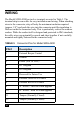

Table Of Contents

8
T
y
c
o
C
O
N
F
I
D
E
N
T
I
A
L
WIRING
The Model SWH-4200 has twelve terminals as noted in Table 3. The
terminal strip is removable for easy installation and wiring. When attaching
wires to the connector, strip off only the minimum insulation required
(approx. 1/8'') and push the wire into the connector until the insulation is
flush or inside the connector body. This is particularly critical for outdoor
readers. While the reader itself is designed and protected to IP65 standards,
the cable wires can potentially corrode and short together if not carefully
mounted and tightly fastened in the connector body.
TABLE 3. Connector Pins for Model SWH-4200
PIN # Description
1 External Beeper Control
2 Ground
3 Power (8 to 16 VDC)
4 D1 Wiegand
5 D0 Wiegand
6 Reserved for Future Use
7 External Green LED Control
8 External Red LED Control
9 A - RS485 - used for Flash upgrade
10 B - RS485 - used for Flash upgrade
11 Tamper (Normally Closed)
12 Tamper (Normally Closed)