TSU 200 Long Distance Reader Wiring and Installation Instructions Art.
Regulatory Notices Europe Hereby, deister electronic GmbH declares that this equipment - if used according to the instructions - is in compliance with the essential requirements and other relevant provisions of the RTTE Directive 1999/5/EC. A full declaration of conformity can be requested at: info@deister-gmbh.de Approved for use in all European countries.
Industry Canada This device complies with Industry Canada licence-exempt RSS standard(s). Operation is subject to the following two conditions: (1) this device may not cause interference, and (2) this device must accept any interference, including interference that may cause undesired operation of the device. Le présent appareil est conforme aux CNR d'Industrie Canada applicables aux appareils radio exempts de licence.
Content 1. Technical Data............................................................5 2. Mechanical Dimensions..............................................6 2.1 Side View...........................................................................................................6 2.2 Front View..........................................................................................................6 2.3 Rear View................................................................................................
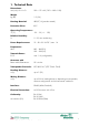
1. Technical Data Dimensions: mm (inch) W x H x D 200 x 175 x 60 (7.87 x 6.89 x 2.36) Weight kg (lbs) 1.2 (2.6) Housing Material: ABS/PC, Al (powder-coated) Protection Class: IP67 Operating Temperature: °C (°F) -20 ... 50 (-4 ... 122) Relative Humidity: % 5...95, non-condensing Power Requierement: 12...28 +20 % VDC / max. 1 A Frequencies: MHz 865 – 868 (EU) 902 – 928 (US) Transmit Power: E.R.P. max.
2. Mechanical Dimensions All Dimensions in mm (inch) 2.1 Side View 2.
2.3 Rear View Attention! M6 Allen screws only! 3. Wiring 3.1 Installation Notes 1) Installing the earth terminal: 1. 2. The earth terminal is supplied with the unit and can be installed at the prepared location when needed, for example when the unit is installed outdoors.
2) Attention: When installing the reader, make sure the tab connector (as shown) is professionally grounded with a flexible line with at least 0.75 mm² (0.11 inch²) (18 gauge) cross section. Connect the earth cable here after installing the earth terminal provided. 3.2 Pin Assignment The TSU 200 has an M12 connector (male) with 4 pins. Pin assignment is as follows: PIN Description 1 +Vcc 2 RS485-A 3 GND 4 RS485-B Because of the line resistance, certain cable lengths should not be exceeded.
Examples: Power Supply Voltage Wire Diameter Maximum Cable Length 12V AWG24 (0,22mm²) 5 m (16.4 ft.) 24V AWG24 (0,22mm²) 50 m (164 ft.) 12V AWG20 (0,5mm²) 10 m (32.8 ft) 24V AWG20 (0,5mm²) 100 m (328 ft.) 4.
5. Mounting 5.1 Mounting on poles and pipes For installation on a mast or tube, the baseplate LRM3 (included in scope of supply, see Section 5.1.1) must be mounted on the rear of the TSU 200, so that it can be adjusted vertically or horizontally. The serrated rear face of the LRM3 ensures that the reader can be securely mounted and adjusted through 360°.
5.2 Montage on walls and ceilings For mounting on walls or ceilings the ball joint bracket LRM1 (optional, see chapter 5.2.1) can be mounted directly onto the back of the reader. This mounting aid allows to adjust the reader in any desired position. Both ends of the ball joint bracket are ball-beared and connected via a rotatable axis. The desired position can be fixed with the included 3/8” Allen wrench. 5.2.1 Mounting with ball joint bracket LRM1 Use Allen screws M6x12 ! 5.2.
5.3 Function Principle and Environmental Influences The reader sends a high-frequency carrier signal. The transponder that is located within the area of this transmitted carrier transmits the signal back with its own transponder data in a modulated way. This very weak signal is being analyzed by the reader. Because of the particular small-bandwidth and the high carrier frequency this system is almost fail-safe. Nevertheless the range of the reader can be negatively influenced.
6. Installation Notes For a standard installation in a passenger-car car park, a TSU 200 can be installed either beside the roadway, or above it. 6.1 Installation on the side of the road: The reader is mounted on a pole on the driver's side next to the road at a height of 1.8 m – 2.0 m (5.9 – 6.5 ft.). Then the reader is aligned towards the transponder/car windshield. When a ground loop is present, it should be used to trigger the reader.
6.3 Reading Distance Given the condition that the transponder is aligned towards the reader, a detection range as shown in the figure below is the result when the reader is operated detached. The reading range varies due to environmental influences. For example, reflections on the ground can increase the maximum reading range. Walls, which are next to a reader, and a different transponder orientation will lead to a deformation of the reading field.
7. Test Mode The TSU 200 has an integrated test mode for checking the performance of UHF transponders, and to automatically adapt the unit's antenna to local environmental conditions. This simplifies alignment of the unit and its adaptation to specific local circumstances of the application. The test mode can be activated with the test transponder TPU 3080T (Art. No. 1388.000) within 30 seconds after the unit is switched on. After activation the antenna is first automatically adjusted.
8. Configuration of WebConfig Software 8.1 Preparations A virtual serial COM port is set up via the USB port. The driver installation is described in the manual of the SNG 3. 8.2 SNG 3 Interface Converter The interface converter SNG3 (optional, see 9. “Accessories”) can be used for connecting a reader to a host/PC via USB. Powering of the reader is carried out by the SNG3 as long as it is connected to a power supply unit itself. To do so, a special wall power supply is available (optional, also see 9.
8.3 Starting WebConfig After the successful installation of the virtual COM port driver, run the WebConfig software. Copy the file "WebConfig.exe" from the supplied CD into a suitable directory on your local hard disk and open it by double-clicking. The configuration of the "TSU 200" must be carried out as follows: Step Configuration Software “WebConfig.
8.3.1 Summary This menu shows a summary of the current reader configuration. Device Info Serial number: Device: Version: Region: Hardware configuration: Serial number of device Identification code of device Firmware version (SW) and hardware version (HW) of device Region the device is authorized for Hardware configuration code of device Note: The picture shows the frequency settings for a European unit. In countries such as e.g. the United States the frequency setup may vary.
8.3.2 Basic Setup Enable RS485 termination If this check box is selected, the internal RS485 termination of the reader is switched on. This function is permanently activated in the TSU 200! read mode This parameter defines, if the reader expects only one tag in the antenna field or if there may be more tags within the antenna field. In case there are more tags, the reader has to execute an anti collision algorithm.
8.3.3 Frequency Setup Preferred channel This value defines the preferred channel number before the reader uses another channel. In a multi-reader environment (EU only), use different channels for the readers. Use the “Preferred channel” parameter to make this setting. Select the greatest possible separation! Channel mask This mask defines the channels to be used by the readers.
Korea Channel No. Frequency E.I.R.P. 2 917.1 MHz ≤ 4.00 W 5 917.7 MHz ≤ 4.00 W 8 918.3 MHz ≤ 4.00 W 11 918.9 MHz ≤ 4.00 W 14 919.5 MHz ≤ 4.00 W 17 920.1 MHz ≤ 4.00 W Japan Channel No. Frequency E.I.R.P. 1 952.4 MHz ≤ 4.00 W 2 952.6 MHz ≤ 4.00 W 3 952.8 MHz ≤ 4.00 W 4 953.0 MHz ≤ 4.00 W 5 953.2 MHz ≤ 4.00 W 6 953.4 MHz ≤ 4.00 W 7 953.6 MHz ≤ 4.00 W Singapore Channel No. Frequency E.R.P. 1 920.25 MHz ≤ 2.00 W 2 920.75 MHz ≤ 2.00 W 3 921.25 MHz ≤ 2.
Brazil Channel No. Frequency E.R.P. 1 915.25 MHz ≤ 2.00 W 2 915.50 MHz ≤ 2.00 W 3 915.75 MHz ≤ 2.00 W 4 916.00 MHz ≤ 2.00 W ... ≤ 2.00 W 47 926.75 MHz ≤ 2.00 W 48 927.00 MHz ≤ 2.00 W 49 927.25 MHz ≤ 2.00 W 50 927.50 MHz ≤ 2.00 W China Channel No. Frequency E.R.P. 1 920,625 ≤ 2.00 W 2 920,875 ≤ 2.00 W 3 921,125 ≤ 2.00 W 4 921,375 ≤ 2.00 W 5 921,625 ≤ 2.00 W 6 921,875 ≤ 2.00 W 7 922,125 ≤ 2.00 W 8 922,375 ≤ 2.00 W 9 922,625 ≤ 2.00 W 10 922,875 ≤ 2.
9. Accessories Article Description Article No. TPU3080T Windshield test transponder. Fixcoded, protected, 01388.000 with deister logo CC2 Connection cable, grey, 3 m, M12 female connector, straight, 4-pin 09287.101 CC4 Connection cable, grey, 3 m, M12 female connector, straight, 4-pin to 4-pin Phoenix connector 09287.301 CC4 Connection cable, grey, 10 m, M12 female connector, straight, 4-pin to 4-pin Phoenix connector 06236.000 LRM1 Ball joint bracket 06103.
Headquarters Germany: deister electronic GmbH Hermann-Bahlsen Str. 11 30890 Barsinghausen Tel.: +49 (0) 51 05 - 51 61 11 Fax: +49 (0) 51 05 - 51 62 17 info.de@deister.com www.deister.com Benelux: deister electronic office Business Park E 19 Battelsesteenweg 455/A 2800 Mechelen Tel.: +32 (0) 15 - 28 09 68 Fax: +32 (0) 15 - 28 09 71 info.be@deister.com France: deister electronic france 101 rue Pierre Semard 92320 Chatillon Tel.: +33 (0) 1 47 - 35 78 78 Fax: +33 (0) 1 47 - 35 92 59 info.fr@deister.