The Chamberlain Group, Inc. 845 Larch Avenue Elmhurst, Illinois 60126-1196 www.liftmaster.com ® GARAGE DOOR OPENER t pa ible with Se De tails Co For Residential Use Only m Model 3850PC r eP fo 9 age 2 Owner’s Manual ■ Please read this manual and the enclosed safety materials carefully! ■ Fasten the manual near the garage door after installation. ■ The door WILL NOT CLOSE unless the Protector System® is connected and properly aligned.
TABLE OF CONTENTS Introduction 2-5 Adjustment Safety symbol and signal word review. . . . . . . . . . . . . . . . 2 Preparing your garage door . . . . . . . . . . . . . . . . . . . . . . . . 3 Tools needed . . . . . . . . . . . . . . . . . . . . . . . . . . . . . . . . . . . 3 Planning . . . . . . . . . . . . . . . . . . . . . . . . . . . . . . . . . . . . . . 4 Carton inventory . . . . . . . . . . . . . . . . . . . . . . . . . . . . . . . . . 5 Hardware inventory . . . . . . . . . . . . . . . . . . . .
Preparing your garage door Before you begin: • Disable locks. • Remove any ropes connected to garage door. • Complete the following test to make sure your garage door is balanced and is not sticking or binding: 1. Lift the door about halfway as shown. Release the door. If balanced, it should stay in place, supported entirely by its springs. 2. Raise and lower the door to see if there is any binding or sticking. If your door binds, sticks, or is out of balance, call a trained door systems technician.
Planning Identify the type and height of your garage door. Survey your garage area to see if any of the conditions below apply to your installation. Additional materials may be required. You may find it helpful to refer back to this page and the accompanying illustrations as you proceed with the installation of your opener. SECTIONAL DOOR INSTALLATION FINISHED CEILING Support bracket & fastening hardware is required. See page 12.
Carton Inventory Your garage door opener is packaged in two cartons which contain the motor unit and all parts illustrated below. Accessories will depend on the model purchased. If anything is missing, carefully check the packing material. Parts may be stuck in the foam. Hardware for installation is also listed below.
ASSEMBLY STEP 1 Attach the Rail to the Motor Unit To avoid SERIOUS damage to opener, ONLY use bolts mounted in top of motor unit. To avoid installation difficulties, do not run the garage door opener until instructed to do so. • Remove the two washered bolts mounted on top of motor unit. • Align rail and styrofoam over belt pulley. Cut tape from rail, belt and styrofoam. • REMOVE STYROFOAM. • Insert both washered bolts through the rail into the motor unit. Tighten bolts securely.
ASSEMBLY STEP 3 Attach the Belt Cap Retainer To avoid possible SERIOUS INJURY to fingers from moving garage door opener: • ALWAYS keep hand clear of belt pulley while operating opener. • Securely attach belt pulley cover BEFORE operating. • Position the belt cap retainer over the motor unit belt pulley so the three holes in cap align with the three holes in mounting plate. Attach with #8x3/8" hex screws provided. You have now finished assembling your garage door opener.
INSTALLATION STEP 1 Unfinished Ceiling Determine the Header Bracket Location Header Wall 2x4 Vertical Centerline of Garage Door To prevent possible SERIOUS INJURY or DEATH: • Header bracket MUST be RIGIDLY fastened to structural support on header wall or ceiling, otherwise garage door might not reverse when required. DO NOT install header bracket over drywall. • Concrete anchors MUST be used if mounting header bracket or 2x4 into masonry.
INSTALLATION STEP 2 Install the Header Bracket Wall Mounting Holes You can attach the header bracket either to the wall above the garage door, or to the ceiling. Follow the instructions which will work best for your particular requirements. Do not install the header bracket over drywall. If installing into masonry, use concrete anchors (not provided). CEILING MOUNT ONLY The nail hole is for positioning only. You must use lag screws to mount the header bracket.
INSTALLATION STEP 3 Attach the Rail to the Header Bracket • Position the opener on the garage floor below the header bracket. Use packing material as a protective base. NOTE: If the door spring is in the way you’ll need help. Have someone hold the opener securely on a temporary support to allow the rail to clear the spring. • Position the rail bracket against the header bracket. • Align the bracket holes and join with a clevis pin as shown. • Insert a ring fastener to secure.
INSTALLATION STEP 4 Position the Opener To prevent damage to garage door, rest garage door opener rail on 2x4 placed on top section of door. Follow instructions which apply to your door type as illustrated. SECTIONAL DOOR OR ONE-PIECE DOOR WITH TRACK A 2x4 laid flat is convenient for setting an ideal door-to-rail distance. • Remove foam packaging. • Raise the opener onto a stepladder. You will need help at this point if the ladder is not tall enough.
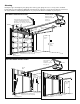
INSTALLATION STEP 5 Hang the Opener Three representative installations are shown. Yours may be different. Hanging brackets should be angled (Figure 1) to provide rigid support. On finished ceilings (Figure 2 and Figure 3), attach a sturdy metal bracket to structural supports before installing the opener. This bracket and fastening hardware are not provided. 1. Remove foam packaging. Measure the distance from each side of the motor unit to the structural support. 2.
INSTALLATION STEP 6 Install the Door Control To prevent possible SERIOUS INJURY or DEATH from electrocution: • Be sure power is not connected BEFORE installing door control. • Connect ONLY to 24 VOLT low voltage wires. To prevent possible SERIOUS INJURY or DEATH from a closing garage door: • Install door control within sight of garage door, out of reach of children at a minimum height of 5 feet (1.5 m) and away from ALL moving parts of door.
INSTALLATION STEP 7 Install the EverCharge ® Standby Power System (Optional) ALWAYS wear protective gloves and eye protection when changing the battery or working around the battery compartment. • Make sure motor unit is unplugged. • Using a Phillips head screwdriver, remove the battery cover on the motor unit. • Partially insert battery into motor unit with terminals facing out. • Connect red (+) and black (-) wires from motor unit to corresponding terminals on battery.
INSTALLATION STEP 9 Attach the Emergency Release Rope and Handle To prevent possible SERIOUS INJURY or DEATH from a falling garage door: • If possible, use emergency release handle to disengage trolley ONLY when garage door is CLOSED. Weak or broken springs or unbalanced door could result in an open door falling rapidly and/or unexpectedly. • NEVER use emergency release handle unless garage doorway is clear of persons and obstructions. • NEVER use handle to pull door open or closed.
INSTALLATION STEP 11 Install The Protector System® Be sure power is not connected to the garage door opener BEFORE installing the safety reversing sensor. To prevent SERIOUS INJURY or DEATH from a closing garage door: • Correctly connect and align the safety reversing sensor. This required safety device MUST NOT be disabled. • Install the safety reversing sensor so beam is NO HIGHER than 6" (15 cm) above garage floor.
INSTALLING THE BRACKETS Be sure power to the opener is disconnected. Install and align the brackets so the sensors will face each other across the garage door, with the beam no higher than 6" (15 cm) above the floor. They may be installed in one of three ways, as follows. Figure 1 DOOR TRACK MOUNT (RIGHT SIDE) Door Track Garage door track installation (preferred): • Slip the curved arms over the rounded edge of each door track, with the curved arms facing the door.
MOUNTING AND WIRING THE SAFETY REVERSING SENSORS • Slide a 1/4"-20x1/2" carriage bolt head into the slot on each sensor. Use wing nuts to fasten sensors to brackets, with lenses pointing toward each other across the door. Be sure the lens is not obstructed by a bracket extension (Figure 5). • Finger tighten the wing nuts. • Run the wires from both sensors to the opener. Use insulated staples to secure wire to wall and ceiling. • Strip 7/16" (11 mm) of insulation from each set of wires.
INSTALLATION STEP 12 Fasten the Door Bracket Fiberglass, aluminum or lightweight steel garage doors WILL REQUIRE reinforcement BEFORE installation of door bracket. Contact your door manufacturer for reinforcement kit. Follow instructions which apply to your door type as illustrated below or on the following page. A horizontal reinforcement brace should be long enough to be secured to two or three vertical supports. A vertical reinforcement brace should cover the height of the top panel.
ONE-PIECE DOORS Please read and comply with the warnings and reinforcement instructions on the previous page. They apply to one-piece doors also. • Center the door bracket on the top of the door, in line with the header bracket as shown. Mark either the left and right, or the top and bottom holes. • Metal Doors: Drill 3/16" pilot holes and fasten the bracket with the 1/4"-14x5/8" self-threading screws provided.
INSTALLATION STEP 13 Connect Door Arm to Trolley Follow instructions which apply to your door type as illustrated below and on the following page. Inner Trolley SECTIONAL DOORS ONLY Make sure garage door is fully closed. Pull the emergency release handle to disconnect the outer trolley from the inner trolley. Slide the outer trolley back (away from the door) about 2" (5 cm) (Figures 1, 2 and 3). Figure 1: • Fasten straight door arm section to outer trolley with the 5/16"x1" clevis pin.
Figure 4 ALL ONE-PIECE DOORS 1. Assemble the Door Arm: • Fasten the straight and curved door arm sections together to the longest possible length (with a 2 or 3 hole overlap). • Make sure the garage door is fully closed. Connect the straight door arm section to the door bracket with the 5/16"x1-1/4" clevis pin. • Secure with a ring fastener.
ADJUSTMENT STEP 1 Program the Travel Limits Without a properly installed safety reversal system, persons (particularly small children) could be SERIOUSLY INJURED or KILLED by a closing garage door. • Incorrect adjustment of garage door travel limits will interfere with proper operation of safety reversal system. • NEVER use force adjustments to compensate for a binding or sticking garage door. • After ANY adjustments are made, the safety reversal system MUST be tested.
ADJUSTMENT STEP 2 Set the Force Without a properly installed safety reversal system, persons (particularly small children) could be SERIOUSLY INJURED or KILLED by a closing garage door. • Too much force on garage door will interfere with proper operation of safety reversal system. • NEVER use force adjustments to compensate for a binding or sticking garage door. • After ANY adjustments are made, the safety reversal system MUST be tested. Door MUST reverse on contact with 1-1/2" (3.
ADJUSTMENT STEP 3 Test the Safety Reversal System Without a properly installed safety reversal system, persons (particularly small children) could be SERIOUSLY INJURED or KILLED by a closing garage door. • Safety reversal system MUST be tested every month. • After ANY adjustments are made, the safety reversal system MUST be tested. Door MUST reverse on contact with 1-1/2" high (3.8 cm) object (or 2x4 laid flat) on the floor. TEST • With the door fully open, place a 1-1/2" (3.
WARNING OPERATION IMPORTANT SAFETY INSTRUCTIONS WARNING To reduce the risk of SEVERE INJURY or DEATH: 1. 2. 3. 4. 5. 6. 7. 8. READ AND FOLLOW ALL WARNINGS AND INSTRUCTIONS. ALWAYS keep remote controls out of reach of children. NEVER permit children to operate or play with garage door control push buttons or remote controls. ONLY activate garage door when it can be seen clearly, it is properly adjusted, and there are no obstructions to door travel.
Using the Wall-Mounted Door Control THE SMART CONTROL PANEL® Press the push bar to Motion Sensing open or close the On/Off door. Press again to reverse the door Prog during the closing cycle or to stop the Hour door while it's Minute opening. This door control Language contains a motion sensing detector that Degrees (F/C) will automatically turn on the light when it detects a person entering the garage.
Using the Remote Control The Remote Control Batteries NOTE: To activate the remote control functions, pull out the plastic pull tab protruding from the remote control housing. This remote control is equipped with a proximity lighting feature. When moving a hand within close proximity to the remote control, the LED lights turn on for 3 seconds. Upon successful activation of a remote control button, the LED lights will blink rapidly.
Install the EverCharge® Standby Power System (Optional) To reduce the risk of FIRE or INJURY to persons: • Disconnect ALL electric and battery power BEFORE performing ANY service or maintenance. • Use only LiftMaster part number 485LMC for replacement battery. • DO NOT dispose of battery in fire. Battery may explode. Check with local codes for disposal instructions. OPERATING INSTRUCTIONS 1. Test the installed battery with the motor unit.
To Open the Door Manually Care of Your Opener MAINTENANCE SCHEDULE Once a Month • Manually operate door. If it is unbalanced or binding, call a trained door systems technician. • Check to be sure door opens and closes fully. Adjust limits and/or force if necessary. (See pages 23 and 24.) • Repeat the safety reverse test. Make any necessary adjustments. (See Adjustment Step 3.
Having a Problem (Troubleshooting) NOTE: Always unplug battery prior to troubleshooting. 1. My door will not close and the light bulbs blink on my motor unit: The safety reversing sensor must be connected and aligned correctly before the garage door opener will move in the down direction. • Verify the safety reversing sensors are properly installed, aligned and free of any obstructions. Refer to Installation Step 11: Install The Protector System ® .
Bell Wire Diagnostics Located On Motor Unit Safety Reversing Sensor “Learn” Button LED or Diagnostic LED Installed Safety Reversing Sensor Your garage door opener is programmed with self-diagnostic capabilities. The “Learn” button/diagnostic LED will flash a number of times then pause signifying it has found a potential issue. Consult Diagnostic Chart below. Diagnostic Chart 1 FLASH Safety reversing sensors wire open (broken or disconnected).
Smart Control Panel ® Messages The following messages are contained within the Smart Control Panel® and may appear during the operations of the unit: Message SAFETY SENSORS CHECK ALIGNMENT, BLOCKAGE OR MISWIRING. SEE OWNER’S MANUAL. Message SAFETY SENSORS MALFUNCTION. CHECK MISWIRING. SEE OWNER’S MANUAL. Message LEARN REMOTE CONTROL. PRESS LEARN BUTTON TO CONFIRM. Message LEARN MODE. PRESS REMOTE CONTROL BUTTON TO PROGRAM REMOTE. Message LOCK MODE. REMOTE CONTROL LOCKED OUT.
PROGRAMMING NOTICE: If this Security✚® garage door opener is operated with a non-rolling code remote control, the technical measure in the receiver of the garage door opener, which provides security against code-theft devices, will be circumvented. The owner of the copyright in the garage door opener does not authorize the purchaser or supplier of the non-rolling code remote control to circumvent that technical measure.
To Add, Reprogram or Change a Keyless Entry PIN NOTE: Your new Keyless Entry must be programmed to operate your garage door opener. USING THE “LEARN” BUTTON 1. Press and release the “learn” button on motor unit. The learn indicator light will glow steadily for 30 seconds. USING THE DOOR CONTROL NOTE: This method requires two people if the Keyless Entry is already mounted outside the garage. 1. Press the Prog button on the door control. LIGHT LOCK 2.
REPAIR PARTS Rail Assembly Parts 5 3 1 6 2 4 KEY NO. 1 2 3 4 7 5 6 7 Installation Parts PART NO. 4A1008 41B5424 41B3869-3A 2777BD 2770BD 41A5434-11 41B4103 83A11-2 DESCRIPTION Master link kit Belt pulley bracket Complete trolley assembly One-piece rail (8' (2.4 m)) One-piece rail (10' (3 m)) Full belt assembly Tensioner assembly Rail grease 5 2 4 KEY PART NO. NO.
Motor Unit Assembly Parts 2 1 11 10 7 3 6 8 4 10 5 9 KEY NO. PART NO. 1 2 3 4 41C76 41B4245 41B4375-3 41A6281 5 6 41D794 41DB002-2 KEY NO. DESCRIPTION Belt cap and sprocket Line cord Terminal block with screws Wire harness kit Complete with: Battery wires and plug light socket wires and plug RPM/passpoint wires with plug Motor with travel module Receiver logic assembly 7 8 9 10 11 37 PART NO.
ACCESSORIES 1702LMC Outside Quick Release: Required for a garage with NO access door. Enables homeowner to open garage door manually from outside by disengaging trolley. 41A5281 Extension Brackets: (Optional) For safety reversing sensor installation onto the wall or floor. 377LMC 915LMC CLOSED OPEN 395LMC 990LMC 373WC SECURITY✚® 3-Button Remote Control : Wood grain plastic case. Includes visor clip. 374LMC SECURITY✚® 4-Button Remote Control : Includes visor clip.
NOTES 39