
Unigy II Spacesaver Installation Manual


Final Assembly Check Procedure
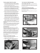
1. For future identification of all cells, number individual
cells in sequence, beginning with number one (1) at the
positive end of the battery. The last cell of the battery is
located at the negative output terminal.
2. Read and record the voltages of the individual cells to
assure that they are connected properly. The total battery
voltage should be approximately equal to the number of
cells connected in series multiplied by the measured
v
oltage of one cell. If the measurement is less, recheck
the connections for proper polarity. Verify that all cell and
battery connections have been properly torqued.
3. Measure and record the intercell connection resistance
using a micro-ohms meter. This helps determine the
adequacy of initial connection installation and can be
used as a reference for future maintenance requirements.
Refer to the recording forms in Appendix C of this
manual. Review the records of each connection and
detail resistance measurements. Clean, remake, and
remeasure any connection that has a resistance
measurement greater than 10% of the average of all the
same type connections (i.e. intercell, intermodule, etc.).
4. Battery performance is based on the output at the battery
terminals. Therefore, the shortest electrical connection
between the battery system and the operating equipment
results in maximum total system performance.
Select cable size based on current carrying capability and
voltage drop.
Cable size should not provide a greater voltage drop between
the battery system and operating equipment than specified.
Excessive voltage drop in cables will reduce the desired
reserve time and power from the battery system.
Parallel Strings
When paralleling valve-regulated batteries, the capacity,
arrangement, and external circuit length should be identical
for each battery. Wide variation in the battery circuit
resistance can result in unbalanced charging (i.e., excessive
charging currents in some batteries and undercharging in
others). As a result, cell failures in one battery string and
subsequent loss of performance capabilities of that string
will result in higher loads in the other parallel string(s),
which may exceed the ratings of the battery connections.
This can damage the battery system and dramatically
shorten battery life.
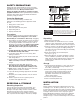
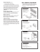
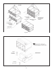
Module Front Shield Assembly
1. Attach one black clip to each end of the clear shield.
(See Fig. 5-4, pg. 16 and 5-5, pg. 5.)
2. Install the fully assembled shield into the tabs on the
module. (See Fig. 5-6, pg. 5 & Fig. 5-4, pg. 16)
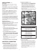
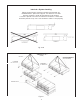
Top Protective Shield Assembly
For side terminal assembly, attach the black top protective
cover to the highest front shield.
For top terminal assembly, cut the black protective cover to
f
it between the terminals and then attach to the front shield.
(See Fig. 5-4, pg. 16.)
Terminal Plate Shield Assembly
For side terminal shield assembly, (Refer to Fig. 5-1, pg 13
for Interlock™ and Fig. 5-2 and 5-2A for Non-Interlock™,
pg. 14 and Fig. 5-7, pg. 5)
For top terminal shield assembly, (Refer to Fig. 5-3, pg. 15
and Fig. 5-8, pg. 5)
Fig. 5-5
Fig. 5-7
Fig. 5-8
Fig. 5-6
5