
User's Manual
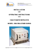
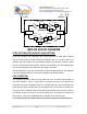
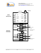
Table Of Contents

Dekolink WIRELESS Ltd.
16 Bazel St. Qiryat-Arieh Petah-Tikva, Israel, 49510
Tel- 972-3-9180-180 Fax-972-3- 190-9180
e-mail: marketing@decolink com web www decolink com
Page
5 of 14 50W rev 4 02/04
BDA MONITOR
The BDA monitor circuit monitors the following functions:
RF power transmitted by the power amplifiers.
For the downlink channel a red fault LED illuminates if the power is 10 dB below the
specified composite power. In normal use the downlink channel continuously transmits
RF signals and this LED should be on. When the donor reception from the base is bad
this LED turns on to warn that the repeater is not being used efficiently. Another green
LED illuminates when the power reaches or exceeds this power (10W). This is used to
set the repeater gain. This limit is the same as the AGC limit and is factory preset.
For the uplink channel a green indicator LED illuminates when the power reaches or
exceeds its composite power (1W). When the isolation between the antennas is bad this
LED lits permanently. This LED should turns on only when a near by cellular is used.
This limit is the same as the AGC limit and is factory preset.
DC voltage of the channels. The fault LED illuminates when the voltage is below or
above the specified limits.
DC current to each of the two LNAs and the uplink power amplifier. If the current is
below or above the specified limits then a LED illuminates.