
User's Manual


Page 3 of 14 50W rev 3 - 11/ 03
Dekolink WIRELESS Ltd.
16 Bazel St. Qiryat-Arieh Petah-Tikva, Israel, 49510
Tel- 972-3-9180-180 Fax-972-3- -
e-mail: marketing@decolink.com web www.decolink.com
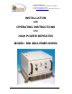
REPEATER OVERVIEW:
The Bi-Directional Repeater assembly provides an exceptional repeater/booster
performance to extend the coverage area of radio communications in buildings
and RF shielded environments.
Features such as high linearity power amplifiers are contributing for the overall
improved system linearity performances. The unit is based on a duplexed path
configuration, having sharp out of band attenuation for improved isolation
between the receiving and transmitting paths.
BLOCK DIAGRAM DESCRIPTION:
The Repeater Downlink path receives the RF signals from base station,
amplifies them and transmits them to the subscriber. The Repeater Uplink path
receives the RF signals from the subscriber, amplifies them and transmits them
to the base station. Two duplexers frequency separate the signals to the proper
amplifying path and isolate the two signals.
For each path two amplifiers do the path signal amplification; a low noise
amplifier (LNA) and a high power amplifier. The low noise amplifier has a 30 dB
step attenuator to set the gain of the specific path.
REPEATER (BDA) CONNECTION
The RF connection is made via two type “N” female connectors. The RF
connector labeled “Base” must be connected to the antenna pointing to the base
station; usually a rooftop antenna. The RF connection labeled “Mobile” must be
connected to the antenna pointing into the area to be covered by the Repeater
such as inside a building or outdoor shaded area.