
User's Manual


D
EKOLINK
W
IRELESS
L
TD
.
C
OMPACT
B
I
-D
IRECTIONAL
A
MPLIFIER
D
EKO
3178B
P
RODUCT
M
ANUAL
Pub. 300TC80031 Rev. 1.55 Proprietary Data Page 7
1.2 D
EKO
3178B
B
LOCK
D
IAGRAM
D
ESCRIPTION
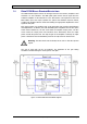
The CBDA Downlink path receives the RF signal from the base station, amplifies it and
transmits it to the subscriber. The BDA Uplink path receives the RF signal from the
subscriber amplifies it and transmits it to the base station. Two triplexers at the Dual
Band BDA’s input and output separate the uplink and downlink frequency bands,
creating high isolation between them and enabling the appropriate amplification of the
signals in each path.
Each path contains two amplifiers and an RF SAW Filter that provides signal filtration
and amplification. In addition, the Dual Band BDA power amplifiers have an ALC option
switch. When switched on, the ALC circuit limits the amplifier output power. The ALC
circuit senses the output power and introduces more attenuation, when the output
power exceeds the preset level. This way the gain of the amplifier is reduced, its output
power is limited and the intermediations products are kept below the desired level.
Warning: The AGC switch must be always ON in order to limit the spurious
signals.
The gain of each path can be set manually. The separation of the gain setting
architecture enables setting the actual gain for each path.
Figure 2. Deko3178B Functional Block Diagram