
Installation Instructions
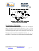
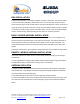
Table Of Contents

Dekolink Wireless Ltd.;16 Bazel St.Qiryat-Arieh Petah-Tikva Israel, 49510
Tel- 972-3-9180-180; Fax-972-3- 190-9180 ;
Email-marketing@dekolink.com
:BDA OVERVIEW
The Compact Bi-Directional Amplifier (CBDA) assembly provides an exceptional
repeater/booster performances to extend the coverage area of radio
communications in buildings and RF shielded environments.
Features such as high linearity power amplifiers are contributing for the overall
improved system linearity performances. The unit is based on a duplexed path
configuration, having sharp out of band attenuation for improved isolation
between the receiving and transmitting paths.
:BLOCK DIAGRAM DESCRIPTION
The CBDA Downlink path receives the RF signals from base station amplifies
them and transmits them to the subscriber. The BDA Uplink path receives the
RF signals from the subscriber amplifies them and transmits them to the base
station. Two duplexers frequency separate the signals to the proper amplifying
path and isolate the two signals.
For each path two amplifiers do the path signal amplification; a low noise
amplifier (LNA) and a high power amplifier. The low noise amplifier has a 30 dB
step attenuator at its output. The step attenuator is used to set the BDA
repeater gain.
The power amplifiers in the BDA have an AGC option switch. When switched on,
the AGC circuit limits the amplifier output power. The AGC circuit senses the
output power and introduces more attenuation, when the output power exceeds
the preset level. This way the gain of the amplifier is reduced, its output power is
limited and the intermodulations products are kept below the desired level.
The AGC amplifier has a Power LED lamp that illuminates when the output
power has reached the preset power limit.
;
Web site- www.dekolink.com rev 5 11/02 page 3 of 12