
Operating Instruction


FCC ID: OIW CBDASMRPS8
Page 4 of 11
BDA OVERVIEW:
The BDA assembly provides an exceptional repeater/booster
performances to extend the coverage area of radio
communications in buildings and RF shielded environments.
Features such as high linearity power amplifiers are contributing
for the overall improved system linearity performances. The unit is
based on a duplexed path configuration, having sharp out of band
attenuation for improved isolation between the receiving and
transmitting paths.
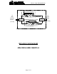
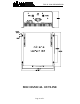
BDA BLOCK DIAGRAM DESCRIPTION:
The BDA Downlink path receives the RF signals from base station
amplifies and transmits them to the subscriber. The BDA Uplink
path receives the RF signals from the subscriber amplifies and
transmits them to the base station. Two duplexers frequency
separate the signals to the proper amplifying path and isolate the
two signals.
BDA with AGC (Option A)
The amplifiers in this BDA have an AGC feedback loop. The AGC
circuit senses the output power and when it exceeds the preset
level of +20 dBm it introduces more attenuation. In this manner the
gain of the amplifier is reduced, its output power is limited to +20
dBm and the Intermodulation products are kept low.
The AGC Dynamic range is 30 dB.