© Dekolink Wireless Ltd.—All Rights Reserved Revision 1.
ABOUT THIS MANUAL This Product Manual provides the following information: • • • • A description of the iDEN Repeater A functional description of the Repeater A description of its main modules Procedures for setup, configuration and checking the proper functioning of the iDEN Repeater • Maintenance and troubleshooting procedures TO WHOM IT IS INTENDED: This Product Manual is intended for experienced technicians and engineers.
DEKOLINK WIRELESS LTD. PRODUCT MANUAL IDEN REPEATER NOTICE Confidential - Authorized Customer Use This document may be used in its complete form only and is solely for the use of Dekolink Wireless Ltd. employees and authorized Dekolink Wireless Ltd. channels or customers. The material herein is proprietary to Dekolink Wireless Ltd. Any unauthorized reproduction, use or disclosure of any part thereof is strictly prohibited.
IDEN REPEATER PRODUCT MANUAL DEKOLINK WIRELESS LTD. SAFETY WARNINGS AND ADMONISHMENTS Throughout this manual, important safety warnings and admonishments are included to warn of possible hazards to persons or equipment. A safety warning identifies a possible hazard and then describes what may happen if the hazard is not avoided. The safety warnings – in the form of Dangers, Warnings and Cautions must be followed at all times.
DEKOLINK WIRELESS LTD. PRODUCT MANUAL IDEN REPEATER GLOSSARY The following is a list of abbreviations and terms used throughout this document.
DEKOLINK WIRELESS LTD. PRODUCT MANUAL IDEN REPEATER CONTENTS 1. Introduction .............................................................................................. 1 1.1 General ........................................................................................................................ 1 1.2 Applications ................................................................................................................. 1 1.3 Features .....................................................
IDEN REPEATER PRODUCT MANUAL DEKOLINK WIRELESS LTD. 4.3.2 Verifying the Link Between the BTS and the Repeater.................................... 11 4.3.3 Verifying the Antenna Isolation .................................................................... 11 4.4 Mechanical Installation .............................................................................................. 12 4.4.1 General ....................................................................................................... 12 4.
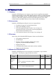
DEKOLINK WIRELESS LTD. PRODUCT MANUAL IDEN REPEATER 1. INTRODUCTION 1.1 GENERAL Dekolink’s iDEN Repeaters are frequency range selective amplifiers that amplify signals bi-directionally between mobile phones and base stations, in cellular and other wireless mobile telephone systems. The iDEN Repeaters can be monitored locally or remotely via Dekolink’s Windows-based Network Management System - RMT software (Refer to the RMT Software User's Guide for more information). 1.
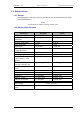
IDEN REPEATER PRODUCT MANUAL DEKOLINK WIRELESS LTD. 1.5 SPECIFICATIONS 1.5.1 General This paragraph provides the electrical, mechanical and environmental specifications of the iDEN Repeater. Note Specifications are subject to change without notice. 1.5.
DEKOLINK WIRELESS LTD. PRODUCT MANUAL IDEN REPEATER 1.5.3 Mechanical Specifications The following table provides the mechanical specifications of the iDEN Repeater. Element Size H x W x D Weight Value 400 x 400 x 260 mm (16 x 16 x 10.3 inch) Approximately 25 kg. (55 lbs.) 1.5.4 Connectors The Repeater interfaces with a Base antenna port and a Mobile antenna port. It includes four external connectors in its bottom panel, as described below.
IDEN REPEATER PRODUCT MANUAL DEKOLINK WIRELESS LTD. 1.6 UNPACKING AND INSPECTION This section provides information for unpacking, inspection and preparation for installation. Examine the shipping container for damage before unpacking the unit. Perform a visual inspection to reveal any physical damage to the equipment. Verify that the equipment is complete, as listed below and under a packing slip. Contact Dekolink Wireless Ltd if any of this equipment is missing.
DEKOLINK WIRELESS LTD. PRODUCT MANUAL IDEN REPEATER 2. FUNCTIONAL DESCRIPTION 2.1 GENERAL This repeater is designed to help improve communications signal by extending the coverage of a base station. The Donor (Base) antenna receives the signal from a base station and conveys it to the iDEN Repeater. The Repeater amplifies the signal. After amplification, the signal is passed through to the Mobile antennas.
IDEN REPEATER PRODUCT MANUAL DEKOLINK WIRELESS LTD. 3. DESCRIPTION 3.1 MAIN COMPONENTS LOCATION Figure 2 provides the location of the main components of the Repeater. A list identifying these components is provided below. Figure 2: iDEN Repeater - Main Components 1. Controller (Control Box - CB) (includes a status LED) 2. Duplexer to Base Antenna (low power) 3. Channeler (Dual Up/Down Converter for Uplink and Downlink Paths) 4. Power Supply 5. Duplexer to Mobile Antenna (high power) 6.
DEKOLINK WIRELESS LTD. PRODUCT MANUAL IDEN REPEATER 3.2 COMPONENTS GENERAL DESCRIPTION A description of the main components of the iDEN Repeater follows. 3.2.1 Channeler The Channeler Module consists of dual Radio Frequency (RF) Up/Down Converter sub- modules for Downlink and Uplink paths. The Channeler amplifies the received RF signals and converts them into an intermediate frequency (IF). The IF outputs are connected to a SAW Filter. The IF outputs are converted back to the original RF frequencies.
IDEN REPEATER PRODUCT MANUAL DEKOLINK WIRELESS LTD. 3.3 REPEATER FEATURES 3.3.1 Controller The integrated Controller Module (Control Box) has three main functions: 1. Detects faults in the repeater and issues an alarm indication. 2. Controls the active components in the Repeater and enables the main parameters setting : Max Power RF Gain, Power On/Off, AGC On/Off SALC On/Off 3. Monitors key operating functions: DC supply voltage Downlink output power Heatsink temperature.
DEKOLINK WIRELESS LTD. PRODUCT MANUAL IDEN REPEATER 3.4.2 ALC Function The Repeater includes the Automatic Level Control (ALC) function on both the Uplink and Downlink power amplifiers to prevent output power from exceeding maximum allowed output power. The amplifier includes a directional coupler and a detector that monitor the output power. The ALC mechanism samples the output power, and decouples and rectifies it.
IDEN REPEATER PRODUCT MANUAL DEKOLINK WIRELESS LTD. 4. INSTALLATION 4.1 SAFETY INSTRUCTIONS Before installing the repeater, review the following safety information: • Follow all local safety regulations when installing the repeaters. • Only qualified personnel are authorized to install and maintain the repeater. • When operating the repeater, it is recommended to keep its cover closed while the power is on. Some maintenance tasks may require the repeater door to be opened while the power is on.
DEKOLINK WIRELESS LTD. PRODUCT MANUAL IDEN REPEATER In case of Indoor coverage, the output power is split into several, omni directional antenna with 0 to 2 dBi typical gain, and distributed to different indoor areas (in building floors, tunnels, basements, parking lots, shopping centers etc.). At least 5 such antennas must be connected to the Repeater with cables and splitters. In this application, the maximum EIRP from each antenna shall not exceed 3W.
IDEN REPEATER PRODUCT MANUAL DEKOLINK WIRELESS LTD. • Measure the coupled output from the Service antenna, using the Spectrum analyzer and LNA if applicable • Perform this procedure across the frequency range of the Uplink bands • Perform this procedure across the frequency range of the Downlink bands • Register the lower result for system operation. 4.4 MECHANICAL INSTALLATION 4.4.1 General The iDEN Repeater enclosure is a cabinet-like unit, made of heavy metal.
DEKOLINK WIRELESS LTD. PRODUCT MANUAL IDEN REPEATER 4.4.4 Tower Mount Installation A tower mount adapter should be attached to the antenna tower prior to mounting the Repeater. The location on the tower and choice of fasteners is governed by local practice. Proceed as with the wall mount installation procedure, refer to paragraph 4.4.3. Pub. 307-2005 Rev. 1.
IDEN REPEATER PRODUCT MANUAL DEKOLINK WIRELESS LTD. Figure 3: iDEN Repeater - Dimensions Figure 45: iDEN Repeater – Typical Outdoor Installation Page 14 Proprietary Data Pub. 307-2005 Rev. 1.
DEKOLINK WIRELESS LTD. PRODUCT MANUAL IDEN REPEATER 4.5 CABLES CONNECTION 4.5.1 General Once the Repeater is installed, you are required to connect the cables from the antennas and to plug to the power supply. 4.5.2 RF Cables Deployment The RF interface between the Repeater and the antennas is supported by one (donor and service) pair of N-type female connectors mounted on the Repeater bottom panel. CAUTION We recommend NOT to connect the antenna cables to the Repeater at this stage.
IDEN REPEATER PRODUCT MANUAL DEKOLINK WIRELESS LTD. 4.5.3 Power Cable Connection The repeater operates from a power source of 110V/220 VAC. The maximum consumption power is 150W. Danger: Electrical Shock This equipment is usually installed outdoors. Wet conditions increase the potential for receiving an electric shock when installing or using electrically powered equipment.
DEKOLINK WIRELESS LTD. PRODUCT MANUAL IDEN REPEATER 5. OPERATING INSTRUCTIONS 5.1 GENERAL This section provides the operating instructions for the Digital Repeater. The operating instructions require the use of the Repeater Management Tool (RMT) software. 5.2 REPEATER MANAGEMENT TOOL (RMT) 5.2.1 General The Repeater Management Tool (RMT) software supplied with the iDEN Repeater provides full access to all control settings and monitoring capabilities.
IDEN REPEATER PRODUCT MANUAL DEKOLINK WIRELESS LTD. Figure 6: iDEN Repeater - Local Monitoring with Laptop 5.4 PC REMOTE CONNECTION To set up a remote connection to a PC (see Figure 7): 1. Install a modem in the iDEN Repeater and connect it to the Controller P3 (RS232) connector or 2. Connect a wireless external modem to the Controller P3 (RS232) connector Figure 7: iDEN Repeater - Remote Monitoring and Control Connection Diagram See Appendix D: Modem Installation for further installation procedures.
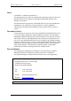
DEKOLINK WIRELESS LTD. PRODUCT MANUAL IDEN REPEATER 5.5 REPEATER INITIALIZATION PROCEDURES To initialize and setup the iDEN Repeater parameters, proceed as follows: 3. Turn on the Laptop or the PC (for remote configuration) 4. Activate the RMT from the Start menu or by double clicking the Repeater Management icon on your desktop 1. The following startup screen is displayed. 2. Click on the Temp Unit button as follows.
IDEN REPEATER PRODUCT MANUAL DEKOLINK WIRELESS LTD. 4. The following Connection screen is displayed. To select the mode of operation for configuration, proceed as follows: 5. After accessing the Repeater, the Password window appears. Enter the Repeater’s password (the default password for the repeater is "password". Click OK. password 6. The main setup screen is displayed.
DEKOLINK WIRELESS LTD. PRODUCT MANUAL IDEN REPEATER Note The changed parameter are colored in red. They turn black after updating. 8. Click the Send Parameters button (not shown above) to update the data. 9. Continue the definition procedure by clicking on the Params. And Control tab. Set the options and check data in two steps as described below. Pub. 307-2005 Rev. 1.
IDEN REPEATER Page 22 PRODUCT MANUAL Proprietary Data DEKOLINK WIRELESS LTD. Pub. 307-2005 Rev. 1.
DEKOLINK WIRELESS LTD. PRODUCT MANUAL IDEN REPEATER 10. Proceed with the definition procedure by clicking on the Repeater Alarms tab. Perform as described below. The iDEN Repeater is now loaded with its own configuration. Pub. 307-2005 Rev. 1.
IDEN REPEATER PRODUCT MANUAL DEKOLINK WIRELESS LTD. 5.6 REPEATER ACTIVATION PROCEDURES To activate the iDEN Repeater parameters, proceed as follows: 1. Use the following procedures to connect the coaxial cables to the Repeater: • Connect the Donor antenna to the BASE port (N-type female connector) in the Repeater lower connectors panel (see Figure 5) • Connect the Service antenna to the MOBILE port (N-type female connector) in the Repeater lower connectors panel 2. Click on the Params. And Control tab.
DEKOLINK WIRELESS LTD. PRODUCT MANUAL IDEN REPEATER 6. MAINTENANCE AND TROUBLESHOOTING 6.1 GENERAL This section provides the maintenance and troubleshooting procedures for the iDEN Repeater. 6.2 PERIODIC MAINTENANCE There is no periodic maintenance required for the iDEN Repeater. As long as it is installed in a shaded area and not subject to extreme temperatures, it will provide long term, carefree operation. 6.3 VISUAL INSPECTION During normal operation, the POWER lamp is on.
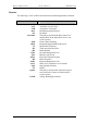
IDEN REPEATER PRODUCT MANUAL DEKOLINK WIRELESS LTD. 6.4.2 Troubleshooting The following table summarizes various error/warning alarms and indications (see Figure 8), their possible cause, and a course of action to correct the problem. Alarm Indication Probable Cause Recommended Action Downlink Power Amplifier FWD Measurement (this is not a fault) Composite output power is below the threshold value - Check the Donor antenna connection.
DEKOLINK WIRELESS LTD. Alarm Indication PRODUCT MANUAL Probable Cause IDEN REPEATER Recommended Action Fan Failure Fan Failed - Check power supply - Check fan. External Alarm Connectivity - Check connection to Alarms connector. Downlink/Uplink Lock Detect alarm Faulty status of the Phased Locked Loop (PLL) in the Channeler unit - Reboot the Repeater. - Check the connection between the Controller and the Channeler (*).
IDEN REPEATER PRODUCT MANUAL DEKOLINK WIRELESS LTD. APPENDIX A: MECHANICAL OUTLINE This appendix contains the mechanical outline of the Repeater. iDEN Repeater - Mechanical Outline Figure 9: iDEN Repeater – Mechanical Outline Page 28 Proprietary Data Pub. 307-2005 Rev. 1.
DEKOLINK WIRELESS LTD. PRODUCT MANUAL IDEN REPEATER iDEN Repeater – Connectors Panel Mechanical Outline The following figure shows the connectors panel layout for Repeater Model Number: MW-CSR-ESMR-25W90 Figure 10: iDEN Repeater – Connectors Panel Layout Pub. 307-2005 Rev. 1.
IDEN REPEATER PRODUCT MANUAL DEKOLINK WIRELESS LTD. APPENDIX B: EXTERNAL ALARMS CONNECTOR PINOUT DEFINITION The following table details the pinout definition of the ALARMS connector located in the gland plate of the repeater.
DEKOLINK WIRELESS LTD. PRODUCT MANUAL IDEN REPEATER APPENDIX D: MODEM INSTALLATION (OPTION) General The iDEN Repeater is ready for connection of a serial, Hayes Compatible, AT Command type modem with a phone number to allow connection in a circuit switched network. If you are using a modem with a SIM card, special settings (network or terminal definitions) may be needed to allow data transmission.
IDEN REPEATER PRODUCT MANUAL DEKOLINK WIRELESS LTD. Connector Pin-out Serial Cable Pin-out for Local Communication between the PC and the Controller: PC Pinout CB Pinout 2 3 3 2 5 5 D-Type 9 Pin female D-Type 9 Pin female Serial Cable Pinout for Remote Communication between the Modem and the Controller: DCE Modem DTE Controller 1 1 2 2 3 3 4 4 5 5 6 6 7 7 8 8 9 9 D-Type 9 Pin female D-Type 9 Pin male Page 32 Proprietary Data Pub. 307-2005 Rev. 1.
DEKOLINK WIRELESS LTD. PRODUCT MANUAL IDEN REPEATER APPENDIX E: DEKOLINK WIRELESS LIMITED WARRANTY Dekolink Wireless [Ltd.] (“Dekolink”), manufacturer of this product (the “Product”) warrants to the original purchaser (“Purchaser”) that the Product is free from defects in materials and workmanship for a term that ends on the earlier of twelve (12) months from the date of activation of the Product or fifteen (15) months from the date of shipment of the Product by Dekolink.