
Installation Manual
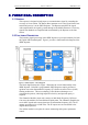
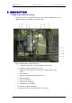
Table Of Contents

DEKOLINK WIRELESS LTD. PRODUCT MANUAL IDEN REPEATER
3.2 COMPONENTS GENERAL DESCRIPTION
A description of the main components of the iDEN Repeater follows.
3.2.1 Channeler
The Channeler Module consists of dual Radio Frequency (RF) Up/Down Converter
sub- modules for Downlink and Uplink paths. The Channeler amplifies the received
RF signals and converts them into an intermediate frequency (IF). The IF outputs are
connected to a SAW Filter. The IF outputs are converted back to the original RF
frequencies. The Channeler also has controllable attenuators (32 dB range in steps of
1dB)and a pre-amplifier for each path.
3.2.2 Monitor Module
The Monitor Module measures the current of the following elements of the Repeater:
Up/Down Converter, Uplink Power Amplifier, and Power Supply. It also senses the
Downlink output power. If a module fails, an appropriate report is sent to the Control
Box and the Summarized alarm red LED lights up.
3.2.3 Controller
The Controller (also called Control Box) controls and monitors the parameters in all
modules of the Repeater. It provides local or remote connection to a PC (See
Dekolink’s RMT User's Guide for more information.).
For a more detailed description of the module, refer to paragraph 3.3.
3.2.4 Power Supply
The Power Supply module allows a wide range of input power from different sources:
90 to 260 VAC, maximum power consumption - 150W.
The output power provided to the Repeater internal modules is:
28 VDC, 15VDC and 9 VDC.
3.2.5 Duplexers
The duplexers isolate the transmit path from the receive path. The pass bandwidth of
the duplexer is the entire width of the Uplink band and the Downlink band
respectively.
3.2.6 Power Amplifier
The power amplifier is the final stage of both the Downlink and Uplink paths. The
iDEN Repeater includes Power Amplifiers with relatively high Third Order Intercept
Point (IP3) figures, thus allowing high output power while preserving high linearity
of the output signals.
Pub. 307-2005 Rev. 1.0 Proprietary Data Page 7