
Installation Manual
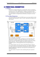
Table Of Contents

DEKOLINK WIRELESS LTD. PRODUCT MANUAL IDEN REPEATER
3.4.2 ALC Function
The Repeater includes the Automatic Level Control (ALC) function on both the
Uplink and Downlink power amplifiers to prevent output power from exceeding
maximum allowed output power.
The amplifier includes a directional coupler and a detector that monitor the output
power. The ALC mechanism samples the output power, and decouples and rectifies
it. The ALC mechanism sends a feedback signal to a voltage variable attenuator
(VVA) that, whenever a high input signal is received, attenuates the signal level so
that the output power of the amplifier does not exceed the preset limit.
The ALC is factory preset to ON state.
3.4.3 RF Gain Setting
The gain range should be set via the RMT in accordance with the input signal power
at the Donor antenna, and the required Downlink output power. Special care should
be taken not to exceed the isolation limit. It is recommended to set the Downlink
path gain to a maximum value that is 12 dB below the isolation between the Base
antenna and the Mobile antenna.
The gain range is 59-90 dB. Use the Max Gain field for Downlink GAIN setting and
the Gain Delta field to determine the GAIN difference between Uplink and Downlink
path (Uplink GAIN follows Downlink GAIN by “Delta” dB)..
Refer to Section 5.5
Note
When you set the gain to 60 dB the Maximum Output Power will degrade due to
overload input power. The maximum input power you can inject is –25 dBm.
Pub. 307-2005 Rev. 1.0 Proprietary Data Page 9