
Installation Manual
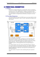
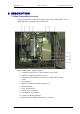
Table Of Contents

DEKOLINK WIRELESS LTD. PRODUCT MANUAL IDEN REPEATER
In case of Indoor coverage, the output power is split into several, omni directional
antenna with 0 to 2 dBi typical gain, and distributed to different indoor areas (in
building floors, tunnels, basements, parking lots, shopping centers etc.). At least 5
such antennas must be connected to the Repeater with cables and splitters.
In this application, the maximum EIRP from each antenna shall not exceed 3W.
Consequently, the minimum required separation distance from any personnel within
the area is 30 cm. Less separation is needed if the power is divided into more than 5
antennas covering many floors or areas.
4.3 REPEATER INSTALLATION SITE VERIFICATION
4.3.1 General
This section provides the required procedures for the verification of the operating
environment of the iDEN Repeater, to be performed before connecting the unit and
before its operation.
4.3.2 Verifying the Link Between the BTS and the Repeater
This test checks the signal strength from the BTS antenna to the iDEN Repeater.
Proceed as follows:
Using Spectrum analyzer, measure the received signal from BTS at the
Donor antenna port near the repeater
•
•
•
•
•
•
Adjust the Donor antenna direction to receive the maximum signal strength.
Compare with the calculated signal strength from the design phase
In case of mismatch, check for cause:
- Antenna out of direction
- Antenna tuned to side lobe instead of main lobe
- Antenna connector or antenna cable faulty
- Line of sight problem (obstruction), etc.
Register the signal strength of the downlink channel for the system
operation phase.
4.3.3 Verifying the Antenna Isolation
The isolation between the Base/Donor and Mobile/Service antennas is critical
especially for high gain, outdoor applications.
For proper operation of the iDEN Repeater, Dekolink recommends that the isolation
between the Donor and Service antennas be at least 12 dB higher than the repeater set
gain.
Note
Lower isolation can lead to high in-band ripple, oscillations and low Signal Quality
Estimate (SQE) measurements.
To measure the isolation, proceed as follows:
Inject a known signal from a signal generator into one antenna (preferably
the Donor antenna)
Pub. 307-2005 Rev. 1.0 Proprietary Data Page 11