
User Manual


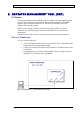
Table Of Contents
- INTRODUCTION
- FUNCTIONAL DESCRIPTION
- DESCRIPTION
- INSTALLATION
- REPEATER MANAGEMENT TOOL (RMT)
- OPERATION
- MAINTENANCE AND TROUBLESHOOTING
- APPENDIX A: MECHANICAL OUTLINE
- APPENDIX B: ALARMS AND LEDS
- APPENDIX C: INSTALLING THE REPEATER IN A LABORATORY SETTING
- APPENDIX D: MODEM INSTALLATION (OPTION)
- APPENDIX E: DEKOLINK WIRELESS LIMITED WARRANTY

DEKOLINK WIRELESS LTD. PRODUCT MANUAL DIGITAL REPEATER
3.2.6 Power Supply
The Power Supply module allows a wide range of input power from different sources:
90 to 260 VAC, maximum power consumption - 350W.
The output power provided to the Repeater internal modules is:
28 VDC or 9 VDC.
3.2.7 Duplexers
The duplexers isolate the transmit path from the receive path. The pass bandwidth of
the duplexer is the entire width of the Uplink band and the Downlink bands
respectively.
3.2.8 Power Amplifier
The power amplifier is the final stage of both the Downlink and Uplink paths. The
Digital Repeater includes Power Amplifiers with relatively high Third Order
Intercept Point (IP3) figures, thus allowing high output power while preserving high
linearity of the output signals.
Pub. 302-2004 Rev. 2.0 Proprietary Data Page 9