
User Manual
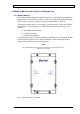


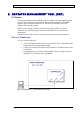
Table Of Contents
- INTRODUCTION
- FUNCTIONAL DESCRIPTION
- DESCRIPTION
- INSTALLATION
- REPEATER MANAGEMENT TOOL (RMT)
- OPERATION
- MAINTENANCE AND TROUBLESHOOTING
- APPENDIX A: MECHANICAL OUTLINE
- APPENDIX B: ALARMS AND LEDS
- APPENDIX C: INSTALLING THE REPEATER IN A LABORATORY SETTING
- APPENDIX D: MODEM INSTALLATION (OPTION)
- APPENDIX E: DEKOLINK WIRELESS LIMITED WARRANTY

DIGITAL REPEATER PRODUCT MANUAL DEKOLINK WIRELESS LTD.
4.3 CONNECTIONS
4.3.1 RF Connections
The connection ports are located in the bottom panel of the Digital Repeater. The RF
connection to the Digital Repeater is made via two N-Type female connectors.
The RF connector labeled “BASE” must be connected to the antenna pointing to the
base station (Donor antenna), which is usually a rooftop antenna, Yagi type or dish..
The RF connection labeled “MOBILE” must be connected to the antenna pointing to
the area covered by the Repeater (Service antenna) such as inside a building or in an
outdoor, RF shaded area.
Note
Do not operate the repeater without terminating the antenna connections with actual
antennas or proper dummy loads.
4.3.2 Connections – Power Requirements
The repeater operates from a power source of 110V/220 VAC. The maximum
consumption power is 350W.
Connect the AC power cable to the AC connector in the Repeater. •
Figure 5: Monitor Module – Bottom Panel
Page 16 Proprietary Data Pub. 302-2004 Rev. 2.0