
User Manual
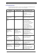
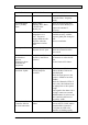
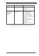
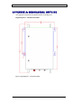
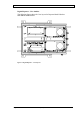
Table Of Contents
- INTRODUCTION
- FUNCTIONAL DESCRIPTION
- DESCRIPTION
- INSTALLATION
- REPEATER MANAGEMENT TOOL (RMT)
- OPERATION
- MAINTENANCE AND TROUBLESHOOTING
- APPENDIX A: MECHANICAL OUTLINE
- APPENDIX B: ALARMS AND LEDS
- APPENDIX C: INSTALLING THE REPEATER IN A LABORATORY SETTING
- APPENDIX D: MODEM INSTALLATION (OPTION)
- APPENDIX E: DEKOLINK WIRELESS LIMITED WARRANTY

DEKOLINK WIRELESS LTD. PRODUCT MANUAL DIGITAL REPEATER
Indication Probable Cause Recommended Action
Increase the RF Gain.
Verify the filters’ frequency
setting.
Downlink Return
Power [VSWR]
alarm
High Voltage
Standing Wave Ratio
(VSWR) at the
Mobile port
Check the antenna and cable
connection at the Mobile port.
Replace the antenna if
necessary.
Temperature alarm Indicates an inner
temperature over
60ºC. The power
supply shutdowns the
Repeater when the
temperature reaches
70ºC
Verify that the repeater is
mounted correctly, with the
Repeater gland plate facing the
floor.
Increase ventilation.
Door Open alarm Indicates that the
Repeater door is open
Close the Repeater door.
Check the connection of the
door switch.
Excessive inter-
modulation or
spurious
frequencies alarm
(External test
equipment)
Amplifier oscillation
caused by insufficient
isolation
Improve the isolation between
the antennas or reduce the RF
gain.
Use the Smart ALC feature.
Excessive noise in
Downlink /Uplink
High input power
causing amplifier
overload
Use the Smart-ALC feature
Reduce the Max Gain in the
Downlink path
Check the input power to the
repeater - should be less than
20 dBm
Check the Channeler LEDs. If
active (red), this indicates that
the input power to the repeater
is high
If the signal in the donor side is
too high, connect an external
10dB attenuator in series to the
Base connector and increase
the gain by 10dB.
Connection to the
Controller failed in
the local connection
Communication
failure
Check the physical connection
between the PC COM1 and the
Controller RS232 interface.
Verify that the LED of the
controller is blinking rapidly.
Pub. 302-2004 Rev. 2.0 Proprietary Data Page 25