
User Manual
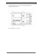

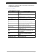
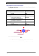
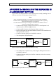
Table Of Contents
- INTRODUCTION
- FUNCTIONAL DESCRIPTION
- DESCRIPTION
- INSTALLATION
- REPEATER MANAGEMENT TOOL (RMT)
- OPERATION
- MAINTENANCE AND TROUBLESHOOTING
- APPENDIX A: MECHANICAL OUTLINE
- APPENDIX B: ALARMS AND LEDS
- APPENDIX C: INSTALLING THE REPEATER IN A LABORATORY SETTING
- APPENDIX D: MODEM INSTALLATION (OPTION)
- APPENDIX E: DEKOLINK WIRELESS LIMITED WARRANTY

DIGITAL REPEATER PRODUCT MANUAL DEKOLINK WIRELESS LTD.
Uplink and Downlink Alarms
A list of Uplink and Downlink alarms is provided below.
Power Amplifier
Uplink Forward Power Amplifier Current Alarm: This alarm is triggered when
the Power Amplifier current is outside of its specified limits.
Downlink Threshold Forward Output Power Alarm: This alarm is triggered
when the Power Amplifier output is lower than the specified limits.
Channeler
This alarm is triggered when the Channeler current is outside of its specified limits.
Channeler Lock-Detect
This alarm is triggered when the Channeler synthesizers are unlocked.
DDF Current
This alarm is triggered when the DDF current (including the internal fan) is outside of
the specified limits.
Voltage Standing Wave Ratio (VSWR)
This alarm is triggered when the return loss of the Downlink antenna or cable
connection exceeds 6 dB (VSWR 3:1).
The VSWR module measures the voltage standing wave ratio of the Downlink output
antenna port. If the VSWR falls below 13 dB, an alarm is triggered.
This alarm provides an indication of the status of the cable connected to the antenna.
If a cable is defective, the VSWR is decreased and the alarm is triggered again. The
alarm can be forwarded to the RMT so that faults and irregularities can be recognized
and eliminated rapidly.
DDF Communication
DDF communication is triggered when the Repeater Controller fails to communicate
with the DDF unit. The communication with digital repeater components is made via
the Control Box. If the Controller fails to read/update parameters with the Digital
Filter module, it triggers the communication alarms.
Measurements
Temperature Measurements: Measures ambient temperature of the digital repeater
chassis. A temperature sensor is placed on the heat sink and provides analog voltage
to the Control Box. The controller processes the input with a formula and provides
the measured temperature.
Downlink Forward Power Measurements: Measures the output power of the
Downlink (if the output power is less than 30 dBm, 30 dBm is displayed.) This
module measures the composite output power in the downlink output path of the
repeater.
Output Power Alarms
If the output power falls below a certain level, an alarm is triggered. You can set the
power level and the mask for the alarm. (See the RMT User's Guide for more
information.) This feature provides you with the output power of the repeater and
thereby achieves optimum output power.
Page 32 Proprietary Data Pub. 302-2004 Rev. 2.0