
User's Manual


PRODUCT MANUAL DEKO4078SD MULTI-CHANNEL SIGNAL BOOSTER DEKOLINK WIRELESS LTD.
P/N 300SC30031 Rev. 1.2 Proprietary Data Page 11
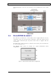
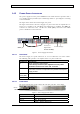
The following figure shows the operation flow in the downlink path and the uplink
path.
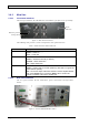
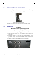
1.4 DEKO4078SD ELEMENTS
The elements are installed in a 19 inch cabinet and are supplied with the necessary
connections except for the RF antenna connections, power (AC outlet) and dry
contact alarm connections (the dry-contact alarm cable is supplied with the
accessories).
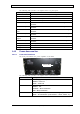
The LEDd of the system elements are all in the front, and the ports and connectors
are accessed from the rear.
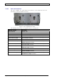
The following figure shows an example of a typical Deko4078SD cabinet
configuration.
Figure 2. Typical Deko4078SD Cabinet Configuration