
User's Manual


PRODUCT MANUAL DEKO4078SD MULTI-CHANNEL SIGNAL BOOSTER DEKOLINK WIRELESS LTD.
P/N 300SC30031 Rev. 1.2 Proprietary Data Page 13
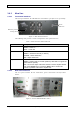
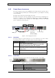
The following table provides a description of the rear panel ports.
Indicator (alarm) Description
Alarms Dry-contact alarm connections (if necessary)
DC Power 28V 28 V DC; 12A
RS485 For Dekolink service personnel
Controls For Dekolink service personnel
DL 800 Pre Output SMA Male Connector – connection to PAU DL800 Pre Input
connector
DL 700 Pre Output SMA Male Connector – connection to PAU DL700 Pre Input
connector
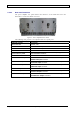
UL 700-800 LNA
Input
SMA Male Connector - connection to PAU UL 700/800 LNA Output
connector
DL 700 LNA Input SMA Male Connector – connection to PAU DL700 Pre LNA Output
connector
UL 700/800 Pre
Output
SMA Male Connector – connection to PAU UL700/800 Pre Input
connector
DL 800 LNA Input SMA Male Connector – connection to PAU DL 800 LNA Output
connector
Modem Future option
Debug 1 N/A - For Dekolink Service Personnel
Debug 2 N/A - For Dekolink Service Personnel
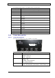
1.4.2 POWER AMPLIFIER UNIT
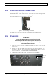
1.4.2.1 Front Panel Interfaces
The front panel includes the power amplifiers’ status LEDs.
The following table provides a description of the status indicators.
Status Indicator Description
Power On Power supply of P.Amp drawer:
GREEN - Power On
GRAY – Power Off
Status Status of P.Amp drawer:
GREEN - OK
ORANGE – Minor malfunction
RED – Major malfunction
Transmit Enable GREEN - System is operable and transmitting a signal
GRAY – No transmission (at all domains – 700 DL; 800DL; UL)
Status LEDs