
User's Manual


PRODUCT MANUAL DEKO4078SD MULTI-CHANNEL SIGNAL BOOSTER DEKOLINK WIRELESS LTD.
Page 14 Proprietary Data P/N 300SC30031 Rev. 1.2
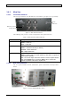
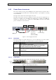
1.4.2.2 Rear Panel Interfaces
The power amplifier rear panel includes the interfaces to the Main unit and to the
Donor/Base and Service/Mobile antennas.
Figure 5. Power Amplifier Rear Panel
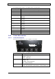
The following table provides a description of the rear panel ports.
Indicator (alarm) Description
DC Power 28V 28 V DC; 12A
RS485 For Dekolink service personnel
Controls For Dekolink service personnel
Service Antenna RF connection to Service/Mobile antenna
(Service) Coupler
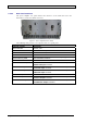
(Service/Donor) 40dB
Coupling connectors (40 dB). Used to test input signals from the
Base and Mobile antennas.
Donor Antenna RF connection to Donor/Base antenna
UL 700/800 LNA Output SMA Male connector - connection to Main unit rear panel UL
700/800 LNA Input connector
DL 700 LNA Output SMA Male connector - connection to Main unit rear panel
DL700 LNA Input connector
DL 800 LNA Output SMA Male connector - connection to Main unit rear panel
DL800 LNA Input connector
DL 800 Pre Input SMA Male connector - connection to Main unit
DL 700 Pre Input SMA Male connector – connection to Main unit rear panel
DL700 Pre Output connector
UL 700/800 Pre Input SMA Male connector – connection to Main unit rear panel
UL700/800 Pre Output connector