
User's Manual


PRODUCT MANUAL DEKO4078SD MULTI-CHANNEL SIGNAL BOOSTER DEKOLINK WIRELESS LTD.
Page 20 Proprietary Data P/N 300SC30031 Rev. 1.2
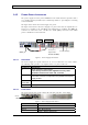
3.4 VERIFYING GROUND CONNECTIONS
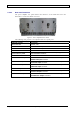
All of the units’ grounding lugs are located on the left side of their rear panels. The
Deko4078SD units’ ground connections are interconnected and the final grounding
connection is performed to the cabinet rack grounding lug located on the left side of
the bottom shelf (accessed from the rear). See below.
Figure 9. Final Grounding Connection
In addition, it is required to connect the rack ground to the building ground.
3.5 POWER UP
ATTENTION!
Be sure that grounding is performed properly and
that all required RF connections (Donor and Service
antennas in case of a supplied cabinet installation)
before powering-up the units
1. Connect the power connector on the Power Supply rear panel to a 220/110 VAC
power source.
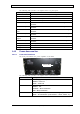
2. Maintain the Main unit in idle state (after power up) for approximately one or
two minutes. This time lapse is required for the CPU boot up. After the boot-up
process is complete, the SYSTEM READY GREEN LED will light.
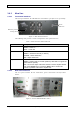
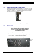
3. Verify that the PWR ON LED on the Main unit front panel is GREEN.
Power On
indicator