Dekolink WIRELESS Ltd. 16 Bazel St. Qiryat-Arieh Petah-Tikva, Israel, 49510 Tel- 972-3-9180-180 Fax-972-3-9180-190 e-mail: marketing@decolink.com web www.decolink.com INSTALLATION AND OPERATING INSTRUCTIONS FOR CELLULAR A+B Fiber-optic REPEATER SYSTEM 50W WITH DIVERSITY & FiberopticBase Interface Unit Page 1 of 1 FO-800AB-50W SYS.
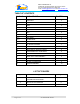
Dekolink WIRELESS Ltd. 16 Bazel St. Qiryat-Arieh Petah-Tikva, Israel, 49510 Tel- 972-3-9180-180 Fax-972-3-9180-190 e-mail: marketing@decolink.com web www.decolink.com TABLE OF CONTENTS PARA No. PARAGRAPH PAGE No. 1. OVERVIEW 3 1.1 FBIU 3 1.2 FBDA 4 2. SUBSYSTEM DESCRIPTION 5 2.1 FBDA 5 2.2 FBIU 5 2.2.1 FIBEROPTIC TRANSCEIVER 5 2.2.2 DUPLEXER 5 2.2.3 ATTENUATOR 5 3 SYSTEM SPECIFICATIONS 7 3.1 RF SPECIFICATIONS 7 3.2 FBDA ALARM SPECIFICATIONS 8 3.
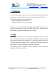
Dekolink WIRELESS Ltd. 16 Bazel St. Qiryat-Arieh Petah-Tikva, Israel, 49510 Tel- 972-3-9180-180 Fax-972-3-9180-190 e-mail: marketing@decolink.com web www.decolink.com 1. OVERVIEW: The Fiber optic repeater system is an excellent solution for BTS coverage extension by means of Fiber optic link and remote high power RF head.
Dekolink WIRELESS Ltd. 16 Bazel St. Qiryat-Arieh Petah-Tikva, Israel, 49510 Tel- 972-3-9180-180 Fax-972-3-9180-190 e-mail: marketing@decolink.com web www.decolink.com 1.2 FBDA The FBDA is installed near the area to be covered and is connected to the mobile antenna. A Fiberoptic transceiver converts the Downlink optical signals to RF signals and the uplink RF signals to optical signals.
Dekolink WIRELESS Ltd. 16 Bazel St. Qiryat-Arieh Petah-Tikva, Israel, 49510 Tel- 972-3-9180-180 Fax-972-3-9180-190 e-mail: marketing@decolink.com web www.decolink.com 2. SUBSYSTEM DESCRIPTION: 2.1 FBDA Please refer to installation and operation instructions for FBDA-800AB-50W-DIV 2.2 FBIU The FBIU is the BTS interface of the system.
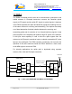
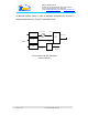
Dekolink WIRELESS Ltd. 16 Bazel St. Qiryat-Arieh Petah-Tikva, Israel, 49510 Tel- 972-3-9180-180 Fax-972-3-9180-190 e-mail: marketing@decolink.com web www.decolink.com for different system setting. In case of separate connections for Rx and Tx , separate attenuators for Rx and Tx should be used. RF IN VAR. ATTN. High pwr ATTN. (MAX. 0dBm) optical in/out F/O+ WDM ATTN. TO BTS RF Out ATTN. F/O RF Out optical in FIG 2: FBIU RF BLOCK DIAGRAM (without duplexer) Page 6 of 6 FO-800AB-50W SYS.
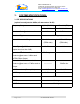
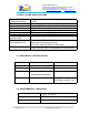
Dekolink WIRELESS Ltd. 16 Bazel St. Qiryat-Arieh Petah-Tikva, Israel, 49510 Tel- 972-3-9180-180 Fax-972-3-9180-190 e-mail: marketing@decolink.com web www.decolink.com 3. SYSTEM SPECIFICATIONS: 3.1 RF SPECIFICATIONS (optical loss adjusted to 0dBm, all attenuators 30 dB) Frequency Range Passband Gain @ min attenuation Passband Ripple Uplink (RX, DIV) Downlink (TX) 824-849 MHz 869-894 MHz 16 dB Nom. 10dB Nom. ± 1.0 dB typical Manual Attenuation Range Noise Figure @+25°C 0 to 16 db cont.
Dekolink WIRELESS Ltd. 16 Bazel St. Qiryat-Arieh Petah-Tikva, Israel, 49510 Tel- 972-3-9180-180 Fax-972-3-9180-190 e-mail: marketing@decolink.com web www.decolink.com 3.
Dekolink WIRELESS Ltd. 16 Bazel St. Qiryat-Arieh Petah-Tikva, Israel, 49510 Tel- 972-3-9180-180 Fax-972-3-9180-190 e-mail: marketing@decolink.com web www.decolink.com 4. INSTALLATION PROCEDURE 4.1 Fiber Optic Link Assembly:(both FBDA and FBIU) 4.1.1 Insert main optical fiber trough the Fiber In/out hole on the FBDA panel and connect it to the Optical In/out connector on the Fiberoptic transceiver. On the FBIU connect the optical fiber to the Optical In/out connector on the Fiberoptic transceiver. 4.1.
Dekolink WIRELESS Ltd. 16 Bazel St. Qiryat-Arieh Petah-Tikva, Israel, 49510 Tel- 972-3-9180-180 Fax-972-3-9180-190 e-mail: marketing@decolink.com web www.decolink.com 4.4 System assembly: 4.4.1 Connect BTS Tx to Tx antenna port on FBIU. (Another 10dB attenuator can be connected to the RF IN port of the Fiberoptic transceiver in the FBIU and the Rotary Attenuator on the FBIU front panel adjusted slightly for system performance optimization). 4.4.
Dekolink WIRELESS Ltd. 16 Bazel St. Qiryat-Arieh Petah-Tikva, Israel, 49510 Tel- 972-3-9180-180 Fax-972-3-9180-190 e-mail: marketing@decolink.com web www.decolink.com Fig. 3: FBIU MECHANICAL LAYOUT Page 11 of 11 FO-800AB-50W SYS.