
Operating Instructions
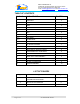
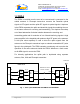
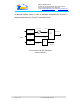
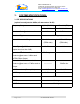
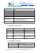

Table Of Contents
- FOR
- CELLULAR A+B
- Fiber-optic REPEATER SYSTEM
- 50W WITH DIVERSITY
- _
- The FBDA is installed near the area to be covered and is connected to the mobile antenna. A Fiberoptic transceiver converts the Downlink optical signals to RF signals and the uplink RF signals to optical signals. A duplexer in the FBDA separates the upli
- of the same antenna for receiving and transmitting. The duplexer has sharp out of band attenuation for better isolation between the receiving and
- transmitting paths and for reduction of out of band interfering signals. A high power amplifier in the downlink path produces high RF power to the antenna. A LNA (low noise amplifier) is used to drive the uplink signals from the antenna to the Fiberopt
- For diversity applications the uplink path is duplicated using separate antenna, filter, LNA and Fiberoptic transmitter.
- Please refer to installation and operation instructions for FBDA-800AB-50W-DIV
- Fig. 3: FBIU MECHANICAL LAYOUT

Dekolink WIRELESS Ltd.
16 Bazel St. Qiryat-Arieh Petah-Tikva, Israel, 49510
Tel- 972-3-9180-180 Fax-972-3- 190-9180
e-mail: marketing@decolink.com
web www.decolink.com
TABLE OF CONTENTS
PARA No. PARAGRAPH PAGE No.
1. OVERVIEW 3
1.1 FBIU 3
1.2 FBDA 4
2. SUBSYSTEM DESCRIPTION 5
2.1 FBDA 5
2.2 FBIU 5
2.2.1 FIBEROPTIC TRANSCEIVER 5
2.2.2 DUPLEXER 5
2.2.3 ATTENUATOR 5
3 SYSTEM SPECIFICATIONS 7
3.1 RF SPECIFICATIONS 7
3.2 FBDA ALARM SPECIFICATIONS 8
3.3 MECHANICAL SPECIFICATIONS 8
3.4 ENVIRONMENTAL CONDITIONS 8
4 INSTALLATION PROCEDURE 9
4.1 FIBER OPTIC LINK ASSEMBLY 9
4.2 DOWNLINK CALLIBRATION 9
4.3 UPLINK CALLIBRATION 9
4.4 SYSTEM ASSEMBLY 10
LIST OF FIGURES
Fig No. Fig. name Page No.
1 FIBEROPTIC REPEATER
SYSTEM BLOCK DIAGRAM
4
2 FBIU RF BLOCK DIAGRAM 6
3 FBIU MECHANICAL LAYOUT 11
Page
2 of
2
FO-800AB-50W SYS.doc