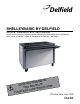
Delfield ™ ® SHELLEYBASIC BY DELFIELD Service, Installation and Care Manual Please read this manual completely before attempting to install or operate this equipment! Notify carrier of damage! Inspect all components immediately. See page 2.
Shelleybasic by Delfield Service & Installation Manual Contents Serial Number Information...................................................... 2 Receiving And Inspecting The Equipment.............................. 2 Specifications ..................................................................... 3-4 Installation.............................................................................. 5 Operation.............................................................................
Shelleybasic by Delfield Service & Installation Manual Specifications Shelleybasic by Delfield Heated Counters Model L D H Ship Wt Food Wells Volts Plug Amp SE-H2 39” 29” 36” 215lbs (98kg) 2 120/208-230 14-20P 10.0/11.0 SE-H3 50” 29” 36” 265lbs (120kg) 3 120/208-230 14-20P 15.0/16.0 SE-H4 64” 29” 36” 320lbs (145kg) 4 120/208-230 14-30P 20.0/22.0 SE-H5 78” 29” 36” 410lbs (186kg) 5 120/208-230 14-50P 24.0/27.
Shelleybasic by Delfield Service & Installation Manual Specifications continued Shelleybasic by Delfield Utility Counters Model L D H Ship Wt SE-U2 39” 29” 36” 150lbs (68kg) SE-U3 50” 29” 36” 170lbs (77kg) SE-U4 64” 29” 36” 200lbs (91kg) SE-U5 78” 29” 36” 230lbs (104kg) SE-U6 92” 29” 36” 280lbs (127kg) Shelleybasic by Delfield Cashier’s Stand Model L D H Ship Wt SE-CS 29” 29” 36” 170lbs (77kg) Shelleybasic by Delfield Tray Stand Model L D H Ship Wt SE-TS 39” 2
Shelleybasic by Delfield Service & Installation Manual Installation Location Units represented in this manual are for indoor use only. Be sure the location chosen has a floor strong enough to support the total weight of the cabinet and contents. A fully loaded model may weigh as much as 3000 pounds! Reinforce the floor as necessary to provide for maximum loading. For the most efficient refrigeration, be sure to provide good air circulation inside and out.
Shelleybasic by Delfield Service & Installation Manual Operation SE-C And SES-C There is a switch on the right side of the compressor stand used to turn the unit on and off. These units are designed to hold cold food product between 33°F to 41°F (0.6°C to 5°C). Cold pans are adjusted at the factory to provide satisfactory operation without any further adjustments. However, if it is necessary to adjust the temperature, the control is located in the machine compartment.
Shelleybasic by Delfield Service & Installation Manual Operation SE-F And SES-F Frost tops are designed to maintain an even layer of frost to pleasantly display desserts and pies. Once turned on, the compressor will run continuously. The unit should be turned off overnight or when not in use. Since it takes time for frost to accumulate initially, the unit should be turned on approximately an hour before it is actually required.
Shelleybasic by Delfield Service & Installation Manual Maintenance Drain Maintenance - Base Each unit has a drain located inside the unit that removes the condensation from the evaporator coil and routes it to an external condensate evaporator pan. Each drain can become loose or disconnected during normal use. If you notice water accumulation on the inside of the unit be sure the drain tube is connected to the evaporator drain pan.
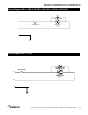
Shelleybasic by Delfield Service & Installation Manual Wiring Diagram SE-C, SES-C, SE-ICE1, SES-ICE1, SE-ICE2, SES-ICE2 CONDENSER FAN S C L1 COOLING T'STAT R COMPRESSOR 115V N G Wiring Diagram SE-F, SES-F ON/OFF SWITCH L1 CONDENSER FAN S C R COMPRESSOR 120V N G Delfield ™ ® For customer service, call (800) 733-8829, (800) 733-8821, Fax (989) 773-3210, www.delfield.
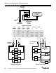
Shelleybasic by Delfield Service & Installation Manual Wiring Diagram SE-H, SES-H PILOT LIGHT (FURNISHED) H1 1000 W - 120V OR 1000/1200 W 208/240 V HEATING ELEMENT P L1 L2 H2 LINE WIRES INFINITE CONTROL WITH “OFF” POSITION TO ADDITIONAL FOOD WARMERS AMPERES IN LINE WIRES # OF WARMERS 1 120V, 1 PHASE 8.3 2 16.7 9.6 10.6 3 4 25 33.3 14.4 19.2 15.9 21.3 14.4/15.9 14.4/15.9 14.4/15.9 19.2/21.3 19.2/21.3 14.4/15.9 5 24 26.6 28.8 31.3 24/26.1 28.8/31.3 19.2/21.3 28.8/31.3 19.2/21.
Shelleybasic by Delfield Service & Installation Manual Wiring Diagram SE-HC2, SES-HC2 CONDENSING UNIT THERMOSTAT M 120V-1PH-3KW HEATER 3-WAY SWITCH HEATER #1 CONTACTOR L1 HEATER #1 THERMOSTAT HEATER #1 LIMIT SWITCH N Wiring Diagram SE-HC3, SES-HC3, SE-HC4, SES-HC4 CONDENSING UNIT THERMOSTAT M 3-WAY SWITCH HEATER #1 CONTACTOR L1 L2 HEATER #1 THERMOSTAT HEATER #1 LIMIT SWITCH N 240V-1PH-5KW HEATER Delfield ™ ® For customer service, call (800) 733-8829, (800) 733-8821, Fax (989) 773-3210,
Shelleybasic by Delfield Service & Installation Manual Wiring Diagram SE-HC5, SES-HC5, SE-HC6, SES-HC6 L1 L2 N (2) 240V-1PH-5KW HEATERS 3-WAY SWITCH CONDENSING UNIT THERMOSTAT M HEATER #1 HEATER #1 CONTACTOR HEATER #2 HEATER #2 CONTACTOR THERMOSTAT HEATER #1 LIMIT SWITCH HEATER #2 LIMIT SWITCH Delfield ™ 12 For customer service, call (800) 733-8829, (800) 733-8821, Fax (989) 773-3210, www.delfield.
Shelleybasic by Delfield Service & Installation Manual Condensing Unit Assembly, Cold Pan Units 1 2 3 4 8 5 7 6 9 1/5 Horse Power, R-134a, Low SE-C2, SES-C2, SE-C3, SES-CE3 Models Key Delfield Part # 1 2183300 2 3526694 3 3516047 4 024-ADB-0040 5 031-264-0000 6 3516172 7 2162691 8 026-ANM-0030 9 3516067 3516191 - Delfield ™ Description Harness, wire, power cord, 8100 Compressor, 1/5 h.p.,115v/60hz Thermostat Compressor stand Bracket, fan motor, blower coil Blade, fan, 5.
Shelleybasic by Delfield Service & Installation Manual Condensing Unit Assembly 1/4 H.P. R404a, Low SE-HC2, SES-HC2, SE-HC3, SES-HC3, SE-HC4, SES-HC4, SE-HC5, SES-HC5, SE-F2, SES-F2, SE-F3, SES-F3, SE-F4, SES-F4, SE-F5, & SES-F5 Models Key 1 2 3 4 5 6 7 8 9 10 11 Delfield Part # 000-BN5-0030 026-C58-0030 3516457 2162717 2160020 3526999 3516443 2194787 3516444 3516322 075-231-0030 3516454 Description Condensing Unit Assembly Shroud, 1/5 HP Condenser Coil Blade, Fan, 7.
Shelleybasic by Delfield Service & Installation Manual Condensing Unit Assembly 1/5 H.P. R404a, Low, SE-ICE1, SE-ICE2 Key 1 2 3 4 5 6 6 7 8 9 10 11 12 - Delfield Part # 026-ANM-0030 3516172 2162691 031-264-0000 3516191 3526997 3526996 3516047 2194787 3516446 3516443 2190154 3516067 2183349 3234188 3516287 Description Baffle, fan, 1/5HP condensing unit Blade, fan, 5.
Shelleybasic by Delfield Service & Installation Manual Food Well Assembly With Thermostat Control SE-HC, SES-HC 2 1 10 Key 1 1 2 3 4 5 6 7 8 9 10 Delfield Part # 2194940 2194942 026-AO6-0042 265-ANQ-003E 2193979 265-ANS-0001 2194190 2194202 3234556 2194185 3516047 Description Immersion heater 120V 1Ph 3KW, 2 pan Immersion heater 240V 1Ph 5KW.
Shelleybasic by Delfield Service & Installation Manual Standard Labor Guidelines To Repair Or Replace Parts On Delfield Equipment Advice and recommendations given by Delfield Service Technicians do not constitute or guarantee any special coverage. • A maximum of 1-hour is allowed to diagnose a defective component. • A maximum of 1-hour is allowed for retrieval of parts not in stock. • A maximum travel distance of 100 miles round trip and 2-hours will be reimbursed.
Shelleybasic by Delfield Service & Installation Manual Standard One Year Warranty (One year parts, 90 days labor.
Shelleybasic by Delfield Service & Installation Manual Notes Delfield ™ ® For customer service, call (800) 733-8829, (800) 733-8821, Fax (989) 773-3210, www.delfield.
Delfield ™ ® Covington, TN Mt. Pleasant, MI Thank you for choosing Delfield! Help is a phone call away. Help our team of professional, courteous customer service reps by having your model number and serial number available at the time of your call (800) 733-8829. Model:_____________________ S/N: ____________________ Installation Date:_____________ For a list of Delfield’s authorized parts depots, visit our website at www.delfield.com. Delfield ™ ® 980 S. Isabella Rd., Mt. Pleasant, MI 48858, U.S.A.