
User's Manual


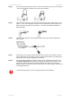
Table Of Contents

Quick Installation Guide Installation
deliberant Page 10
Step 4. For pole mounting attach APC 2M-14 on pole with U bolt (items H and J in the Figure 1
– APC 2M-14 Package Contents) as shown in picture below:
Step 5. Connect Ethernet cable into the APC 2M-14 then insert a rubber gasket (item F in the
Figure 1 – APC 2M-14 Package Contents) into CAT5 Ethernet connector gland and
tighten with gland cap (item E in the Figure 1 – APC 2M-14 Package Contents) as
displayed below:
Step 6. Connect power adapter into PoE injector together with UTP cables as displayed in
picture below:
Step 7. Power-up the unit. The green Power LED must be on (refer at the respective section
LEDs). Depending on link quality, up to four yellow LEDs will switch on indicating that
link between two units was established successfully.
Step 8. After the link was established, align the antenna for the maximum performance. Run
the Antenna Alignment tool in the Web management interface and move the unit in
the horizontal and vertical planes until the maximum RSSI visible on the Antenna
Alignment graph is achieved. After the maximal RSSI is reached, tighten down the unit
in the optimum position.
Avoid standing directly in front of an operating antenna while aligning.