
User's Manual


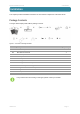


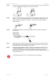
Table Of Contents

Quick Installation Guide Installation
deliberant Page 9
LEDs
The APC 2M-14 has 6 LEDs located on the side panel: power, LAN and 4 RSSI LEDs (refer at the
Figure 2 – APC 2M-14 Overview for details). The various states of the LEDs indicate different
connection operations as follows:
LED
Color
Status
Indication
Power
Green
On
APC 2M-14 is active/working
Off
No power on APC 2M-14
LAN
Green
On
LAN connection exists.
Blinking
Indicates the traffic on LAN interface.
Off
No LAN connection.
RSSI (1, 2, 3, 4)
Yellow
On
The RSSI level has reached the appropriate threshold
level (default RSSI threshold levels: 10, 25, 35, 50)
Off The RSSI level has not reached the appropriate
threshold level
Assembling and mounting the APC 2M-14
The APC 2M-14 unit’s mounting bracket is designed to make installation on a wall or a pipe easy.
After the unit is attached, its position is fixed with the single bolt. Follow the steps for APC 2M-14
assembling:
Step 1. Make sure that the APC unit is powered-off.
Step 2. Ground the APC 2M-14 unit. The unit must be properly grounded to protect against
lightning. The grounding wire must be attached to the grounding stud on the unit (refer
at the Figure 2 – APC 2M-14 Overview).
If the unit is attached to a metal pipe which is earth-grounded, no further grounding is
required.
Step 3. Attach mounting hardware (item C in the Figure 1 – APC 2M-14 Package Contents) to
the unit and tighten with the nut and bolt (items I and J in the Figure 1 – APC 2M-14
Package Contents).
For wall mounting, first attach the mounting bracket to the wall and then connect the unit
together and tighten the nut and bolt.
It is recommended not to tighten the unit to its mounting hardware until the alignment
process of the antenna is complete.