
User's Manual


deliberant Page 10
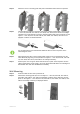
Step 4. Attach the unit to a mounting plate and push it downwards until it clicks into position:
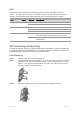
Step 5. Connect Ethernet cable into the APC then insert a rubber gasket (item H in the Figure
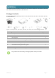
1 – APC 2M, APC 5M, APC 5M V2, APC 2M-8, APC 5M-12, APC 5M-12 V2 Package
Contents) into CAT5 Ethernet connector gland and tighten with gland cap (item G in the
Figure 1 – APC 2M, APC 5M, APC 5M V2, APC 2M-8, APC 5M-12, APC 5M-12 V2
Package Contents) as displayed below:
It is recommended to use shielded STP Ethernet cable to reduce exposure of the
electromagnetic noise.
Step 6. After attaching the APC to the mounting plate, fasten the unit to the bottom near the
CAT5 Ethernet plug using screw (item E in the Figure 1 – APC 2M, APC 5M, APC 5M
V2, APC 2M-8, APC 5M-12, APC 5M-12 V2 Package Contents).
Step 7. Power-up the unit. The green Power LED must be on (refer at the respective section
LEDs). Dependently on link quality, up to four yellow LEDs will switch on indicating that
link between two units was established successfully.
Wall Mounting
Step 1. Make sure that the APC unit is powered-off.
Step 2. Attach APC mounting plate (item C in the Figure 1 – APC 2M, APC 5M, APC 5M V2,
APC 2M-8, APC 5M-12, APC 5M-12 V2 Package Contents) to the wall using screws
(item J in the Figure 1 – APC 2M, APC 5M, APC 5M V2, APC 2M-8, APC 5M-12, APC
5M-12 V2 Package Contents) as displayed below: