User manual Revision 1.0 16 May 2013 Copyright © 2012 Deliberant www.deliberant.
Copyright © 2012 Deliberant This user’s guide and the software described in it are copyrighted with all rights reserved. No part of this publication may be reproduced, transmitted, transcribed, stored in a retrieval system, or translated into any language in any form by any means without the written permission of Deliberant. Notice Deliberant reserves the right to change specifications without prior notice.
Le présent appareil est conforme aux CNR d'Industrie Canada applicables aux appareils radio exempts de licence.L'exploitation est autorisée aux deux conditions suivantes : (1) l'appareil ne doit pas produire de brouillage, et (2) l'utilisateur de l'appareil doit accepter tout brouillage radioélectrique subi, même si le brouillage est susceptible d'en compromettre le fonctionnement.
Contents Copyright ............................................................................................................................................. 2 Notice .................................................................................................................................................. 2 FCC Caution........................................................................................................................................ 2 IC warning ................................
Basic Wireless Settings............................................................................................................................. 38 Security Settings ....................................................................................................................................... 39 Advanced Wireless Settings...................................................................................................................... 40 Wireless Mode: iPoll Access Point ....................
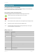
User Manual About this Guide Prerequisite Skills and Knowledge To use this document effectively, you should have a working knowledge of Local Area Networking (LAN) concepts and wireless Internet access infrastructures. Conventions Used in this Document The following typographic conventions and symbols are used throughout this document: Additional information that may be helpful but which is not required. Important information that should be observed.
User Manual Abbreviation Description MAC Media Access Control Mbps Megabits per second MHz Megahertz MIMO Multiple Input, Multiple Output MSCHAPv2 Microsoft version of the Challenge-handshake authentication protocol, CHAP.
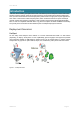
User Manual Introduction DLB APC offers reliable, great performance and cost-effective point-to-multipoint outdoor and indoor wireless solutions perfectly suited for access technology, private network and hotspots. Beside that APC (Access Point/Customer Premises Equipment) can be used for a light point-to-point applications. APC works in unlicensed 2.4 GHz frequency band, which is attractive solution for quick and simple network creation with minimum investment.
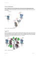
User Manual Point to Multipoint This is the IEEE 802.11n wireless multipoint which delivers several times higher throughput than 802.11g. The APC supports a private wireless point to multipoint protocol called iPoll which allows connecting more than one iPoll Stations to the iPoll Access Point thus creating a robust point to multi point network.
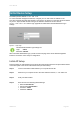
User Manual Initial Device Setup The default product address is 192.168.2.66. To access the Web management interface, configure your PC with a static IP address on the 192.168.2.0 subnet with mask 255.255.255.0. Connect the AP device in to the same physical network as your PC. Open the Web browser and type the default IP address of the APC device https://192.168.2.66/ and the login page will be loaded.
User Manual The initial login screen looks as follow: Step 5. Confirm the disclaimer of the APC. According to the chosen country the regulatory domain settings may differ. You are not allowed to select radio channels and RF output power values other the permitted values for your country and regulatory domain. Step 6. Enter the default password, and then press the Login button to enter the AP web management page.
User Manual Step 7.
User Manual Step 8.
User Manual Step 9. Verify connection. Navigate to Status | Information menu to check if the Station are successfully connected to the APC device: Initial Station Setup Follow the steps for initial wireless client setup that will be connected to the previously configured AP (refer to the section Initial AP Setup). Step 1. Connect an Ethernet cable between your computer and the DLB APC device. Step 2. Make sure your computer is set to the same subnet as the APC, i.e. 192.168.2.150 Step 3.
User Manual The initial login screen looks as follow: Step 5. Confirm the disclaimer of the APC. According to the chosen country the regulatory domain settings may differ. You are not allowed to select radio channels and RF output power values other the permitted values for your country and regulatory domain. Step 6. Enter the default password, and then press the Login button to enter the APC web management page.
User Manual Step 7.
User Manual Step 8. deliberant Navigate to the Configuration | Wireless tab, choose Station WDS wireless mode, click Scan button near the SSID entry field to choose the SSID of the AP where the station will be associated to.
User Manual Step 9. deliberant Verify connection. Navigate to the Status | Information page. The Information page will display wireless information of the link with AP.
User Manual Network Operation Modes The device can operate as transparent Bridge or Router. Bridge Mode The device can act as a wireless network bridge and establish wireless links with other APs. In this mode all LAN port and Wireless interface will be a part of the Bridge. Figure 5 – Bridge Mode With a Bridge, all connected computers are in the same network subnet. The only data that is allowed to cross the bridge is data that is being sent to a valid address on the other side of the bridge.
User Manual General Device Operation Web Management Structure The main web management menu is displayed after successfully login into the system (see the figure below). From this menu all essential configuration pages are accessed. The active menu tab is displayed in a different color: Figure 7 – AP Web Management Menu By default the Status | Information menu is activated where the main device information is displayed.
User Manual Wireless – specify wireless mode (AP, Station, Station WDS, iPoll AP, iPoll Station), country, SSID, IEEE mode, channel configuration, security and advanced radio settings. Virtual AP – create and setup virtual AP (only in AP wireless mode). Wireless ACL – access control by MAC address (only in AP and IPoll AP wireless modes). Traffic shaping – download and upload traffic control. Port forwarding – port forwarding rules (only in router network mode for AP and IPoll AP).
User Manual Configuration Guide This document contain product‘s powerful web management interface configuration description allowing setups ranging from very simple to very complex. Status Information The Information page displays a summary of status information of your device. It shows important information for the APC operating mode, network settings. Figure 8 – Device Information System information – displays general information about the device.
User Manual Network The Network sections displays statistics of the network interfaces and DHCP leases (depending on network mode): Figure 9 – Network Statistics Interface – displays the interface name. The SSID name is displayed in the brackets near the radio interface (and VAPs). IP address – displays the IP address of the particular interface. MAC – displays the MAC address of the particular interface. Received – displays the number of received packets.
User Manual The Wireless statistics displays the receive/transmit statistics between AP and successfully associated wireless clients: Figure 10 – Access Point's Wireless Statistics In case the access point has more than one wireless interface (VAPs), the appropriate number of tables with information about connected wireless clients will be displayed. Peer MAC – displays MAC address of the successfully connected wireless client.
User Manual ARP The ARP page displays the ARP (Address Resolution Protocol) table currently recorded on the device. Use Refresh button to reload ARP table results. Figure 12 – ARP Table Records Configuration Network The Configuration | Network page allows you to control the network configuration and settings of the device. First, the device operation mode must be defined to work as a bridge or router.
User Manual When device is configured to operate in Bridge mode, only device LAN settings should be configured on the Network page: Figure 14 – Bridge Mode Settings IGMP snooping (only on AP or iPoll Bridge modes) – when enabled AP will passively snoop on IGMP Report and Leave packets transferred between it's clients and IP Multicast hosts. It checks IGMP packets passing through it, picks out the group registration information and generates internal L2 MAC forwarding table.
User Manual VLAN to SSID Mapping Virtual Local Area Networks (VLANs) are logical groupings of network resources. Figure 15 - VLAN to SSID Mapping VLAN to SSID mapping – specify the VLAN ID for traffic tagging on required radio interface [2-4095]. The Station devices that associate using the particular SSID will be grouped into this VLAN. Management VLAN Available only on Bridge network mode. Access to the AP for management purposes can further be limited using VLAN tagging.
User Manual Router Mode This section allows customizing parameters of the Router to suit the needs of network, including ability to use the built-in DHCP server. When device is configured to operate as Router, the following sections should be specified: WAN network settings, LAN network settings and LAN DHCP settings.
User Manual WAN Settings WAN network settings include settings related to the WAN interface. The access type of the WAN interface can be configured as: Static IP, Dynamic IP, PPPoE client. WAN mode – choose Static IP to specify IP settings for device WAN interface: Figure 18 – Router WAN Settings: Static IP MAC address – specify the clone MAC address if required. The ISPs registers the MAC address of the router, and allows only that MAC address to connect to their network.
User Manual WAN mode – choose Dynamic IP to enable DHCP client on the WAN side. This option does not need any parameters: Figure 19 – Routers WAN Settings: Dynamic IP MAC address – specify the clone MAC address if required. The ISPs registers the MAC address of the router, and allows only that MAC address to connect to their network.
User Manual WAN mode – choose PPPoE to configure WAN interface to connect to an ISP via a PPPoE: Figure 20 – Routers WAN Settings: PPPoE client MAC address – specify the clone MAC address if required. The ISPs registers the MAC address of the router, and allows only that MAC address to connect to their network.
User Manual Figure 21 – Router LAN Settings IP address – specify the IP address of the device LAN interface. Subnet mask – specify the subnet mask of the device LAN interface. LAN DHCP Settings DHCP mode – choose disabled to disable DHCP on LAN interface. Figure 22 – Router LAN Settings: DHCP Disabled DHCP mode – choose relay to enable DHCP relay. The DHCP relay forwards DHCP messages between subnets with different sublayer broadcast domains.
User Manual Wireless The Wireless tab is divided in three sections: Basic, Security and Advanced configuration sections. The Basic section contains all parameters that required to configure in order have working wireless link. Security section is used to select authentication and encryption settings. Advanced section contains parameters allowing optimizing the link capacity. Before changing radio settings manually verify that your settings will comply with local government regulations.
User Manual Wireless Mode: Access Point (auto WDS) Use Basic Wireless Settings to setup radio interface of the device. Figure 26 – Access Point Wireless Settings Basic Wireless Settings SSID – specify the SSID of the wireless network device. Broadcast SSID – enables or disables the broadcasting of the SSID for AP. IEEE mode – specify the wireless network mode. Channel width – The default channel bandwidth for 802.11 radio is 20MHz. The 802.
User Manual Security Settings Both sides (AP and Station) of the link must have the same security settings. Device supports various authentication/encryption methods: Open – no encryption. WEP – 64bit and 128bit key. Personal – preshared key encryption with WPA/WPA2 using AES or TKIP. Enterprise – RADIUS server based authentication with WPA/WPA2 encryption using AES or TKIP (requires configured RADIUS server). UAM – Web browser based user authentication method.
User Manual AP has possibility to configure Enterprise WPA/WPA2 encryption with RADIUS authentication. Properly configured AP will accept wireless stations requests and will send the information to configured RADIUS server for client authentication. Figure 30 – Security: Enterprise WPA/WPA2 Encryption The properly configured RADIUS server is required for Enterprise WPA/WPA2 encryption.
User Manual Tx power – set the unit’s transmitting power at which the device will transmit data. The larger the distance, the higher transmit power is required. To set transmit power level use the slider or enter the value manually. When entering the transmit power value manually, the slider position will change according to the entered value. The maximum transmit power level is limited to the allowed value by country in which device is operating regulatory agency.
User Manual Wireless Mode: Station Station WDS has the same wireless settings. The Station wireless settings a bit differ from the Access Point’s settings: there is possibility to scan SSID of the surrounding APs and choose the required one. Use Wireless Settings to setup radio interface of the device. Figure 32 – Station Wireless Settings Basic Wireless Settings SSID – specify the SSID of the wireless network device. Scan – click this button to scan for surrounding wireless networks.
User Manual Security Settings Both sides (AP and Station) of the link must have the same security settings. Device supports various authentication/encryption methods: Open – no encryption. WEP – 64bit and 128bit key. Personal – preshared key encryption with WPA/WPA2 using AES or TKIP. Enterprise – RADIUS server based authentication with WPA/WPA2 encryption using AES or TKIP (requires configured RADIUS server).
User Manual Figure 36 – Security: Enterprise WPA/WPA2 Encryption Encryption – choose WPA/WPA2 encryption type: AES – data encrypted with AES method; TKIP – data encrypted with TKIP method; EAP method – choose EAP method: EAP-TTLS-MSCHAPv2 PEAP/ MSCHAPv2 Identity – specify the identity of the authentication to the RADIUS server. Password – specify the password of the authentication to the RADIUS server.
User Manual Fragmentation – specify the Fragmentation threshold using slider or enter the value manually [2562346 bytes]. This is the maximum size for a packet before data is fragmented into multiple packets. Setting the Fragmentation threshold too low may result in poor network performance. Only minor modifications of this value are recommended. RTS – specify the RTS threshold using slider or enter the value manually [0-2347 bytes].
User Manual Figure 38 – iPoll Access Point’s Wireless Settings Basic Settings Use Basic section to setup basic operating settings of the iPoll Access Point’s radio. iPoll Access Point and iPoll Station will operate in 802.11n IEEE mode only. SSID – specify the SSID of the wireless network device. Broadcast SSID – enables or disables the broadcasting of the SSID for iPoll AP. Channel width – The default channel bandwidth for 802.11n radio is 20MHz. The 802.
User Manual By default there is no encryption enabled on the device: Figure 39 – iPoll Security: Open Personal WPA/WPA2 encryption must be specified with the pre-shared key: Figure 40 – iPoll Security: Private WPA/WPA2 Encryption Passphrase – specify the WPA or WPA2 passphrase [8-63 characters]. The passphrase will be converted to key format, selected above.
User Manual Wireless Mode: iPoll Station The iPoll Station is a wireless client mode which can connect to the iPoll Access Points. Figure 42 – iPoll Station's Wireless Settings Basic Settings Use this section to setup basic operating settings of the iPoll Station radio. iPoll Access Point and iPoll Station will operate in 802.11n IEEE mode only. SSID – specify the SSID of the wireless network device manually, or use Scan functionality.
User Manual Open – no encryption. Personal WPA – preshared key encryption with WPA using AES method. Personal WPA 2 – preshared key encryption with WPA2 using AES method. By default there is no encryption enabled on the device: Figure 43 – iPoll Security: Open Personal WPA/WPA2 encryption must be specified with the pre-shared key: Figure 44 – iPoll Security: Private WPA/WPA2 Encryption Passphrase – specify the WPA or WPA2 passphrase [8-63 characters].
User Manual Max data rate – select the device data transmission rates in Mbps from the drop-down list. The unit will attempt to transmit data at the highest data rate set. If there will be an interference encountered, the iPoll Station will step down to the highest rate that allows data transmission. Virtual AP Virtual AP functionality is available only in Access Point (auto WDS) wireless mode. Use the Configuration | Virtual AP page to configure to create up to 3 additional Virtual AP interfaces.
User Manual Personal – preshared key encryption with WPA/WPA2 using AES or TKIP. Enterprise – RADIUS server based authentication with WPA/WPA2 encryption using AES or TKIP (requires configured RADIUS server). UAM – Web browser based user authentication method. UAM authentication is available only if Access Point is working in router mode. For UAM configuration details refer at the respective chapter Universal Access Method (UAM).
User Manual Figure 49 – Traffic Shaping Configuration Limit all traffic Enable download shaping – select to enable limitation of the download traffic. Download limit, kbps – specify the maximum download (from wireless interface to Ethernet interface) bandwidth value in Kbps. Download burst, kbytes – specify the download burst size in kbytes. Enable upload shaping – select to enable limitation of the upload traffic.
User Manual Port Forwarding Port forwarding is active only in Router network mode.. Port Forwarding, UPnP and DMZ is effective only if NAT is enabled. The Port forwarding section gives the ability to pass traffic behind an interface that has NAT enabled. For instance if the unit is in router mode with NAT enabled on the WAN interface, no devices on the outside of the WAN interface can see any private IPs on the LAN side of the unit.
User Manual Static Routes Static routes is active only in Router network mode. A routing rule is defined by the destination subnet (Destination IP address and netmask) and/or gateway where to route the target traffic. To add a new static route, specify the following parameters: Figure 52 – Static Route Configuration Destination IP – specify the destination IP address. Netmask – specify destination netmask. Gateway – specify the gateway address for the route. 0.0.0.
User Manual System alerts The device is able to send external alerts when there are system errors. The alerts can be sent via SNMP Traps or/and SMTP notifications. Figure 53 – Device Alerts Enable alerts – select to enable alert notifications on the system. System check interval, s – specify interval in seconds at which the device will send notifications of unexpected system behavior. System alerts: Wireless link status change – system will send notification on Wireless link status change.
User Manual SNMP Traps Settings Manager address – specify the IP address or hostname of SNMP Trap receiver. Manager port – specify the port number of the Trap receiver. Default port number is 162. Trap community - specify the SNMP community string. This community string acts as password between SNMP manager and device by default Trap community string is "public". Use inform – select to wait for an acknowledgment from SNMP manager that trap was received.
User Manual Link location – displays the physical location of the device. This name has the same value as Device location in the Device settings. Contact information – specify the identification of the contact person for this managed device, together with information on how to contact this person. R/O community – specify the read-only community name for SNMP version 1 and version 2c. The read-only community allows a manager to read values, but denies any attempt to change values.
User Manual SSH Use this menu to manage access to the device via SSH port: Figure 58 – SSH Port Configuration Enabled – enable or disable SSH access to device. Port – the SSH service port. By default SSH port is 22. HTTP Use this menu to control HTTP connection on device web management: Figure 59 – HTTP Settings Enable management through HTTP – select tis option to enable or disable HTTP access to the device management. Port – specify HTTP port. Standard HTTP port is 80.
User Manual System Administration For security reasons it is recommended to change the default administrator username and password as soon as possible. System menu allows you to manage main system settings and perform main system actions (reboot, restore configuration, etc.). The section is divided into further three sections: Device settings, Account settings and system functions.
User Manual System functions Reboot device – reboot device with the last saved configuration. Reset device to factory defaults – click to restore unit's factory configuration. Resetting the device is an irreversible process. Current configuration and the administrator password will be set back to the factory default. Download troubleshooting file – click to download the troubleshooting file.
User Manual Forward port – specify the port to which syslog messages will be forwarded [0-65535]. Default: 514. Forward message level – specify the level of the message which will be sent to the remote syslog server. The level determines the importance of the message and the volume of messages generated by the device. The levels are in order of increasing importance [emergency/alert/critical/error/warning/notice/information/debug]. Default: information.
User Manual Firmware Upgrade To update your device firmware use the System | Firmware upgrade menu. Press Upload firmware, select the firmware file and click the Upload firmware button: Figure 64 –Firmware Upload Current version – displays version of the current firmware. Upload firmware – click the button to select the new firmware image for uploading it to the device. The device system firmware upgrade is compatible with all configuration settings.
User Manual Tools Antenna Alignment The Antenna Alignment tool measures signal quality between the Station and AP. For best results during the antenna alignment test, turn off all wireless networking devices within range of the device except the device(s) with which you are trying to align the antenna. Watch the constantly updated display in the Alignment Test window as you adjust the antenna. Figure 66 – Antenna Alignment Start – press this button to start antenna alignment.
User Manual To perform the Site Survey test currently, click the Start scan: Figure 67 – Site Survey Results 1 Last updated before – displays when the last scan was performed. The results of the Site Survey test are converted to handy two graphs: AP count and RSSI. An administrator can use this to identify the best channel for device operation that will not receive interference from adjacent APs.
User Manual Delayed Reboot This tool is extremely useful while tuning radio settings – once you defined hypothetic radio parameters and set them with Apply button (not written to the permanent memory), device starts operating with the new settings, and in case the link fails, device will be rebooted in specified minutes, thus the old settings will be set back. Figure 69 – Delayed Reboot Configuration Reboot after – specify time in minutes, after which the device will be rebooted.
User Manual Traceroute This tool is a route-tracing utility used to determine the path that an IP packet has taken to reach a destination. This is useful when trying to find out why destination is unreachable, as you will be able to see where the connection fails. Figure 71 – Traceroute Results Destination IP or Hostname – specify hostname or IP address of the target host. Max Hops –Specifies the maximum number of hops to search for target. Start/Stop – click to start or stop traceroute tool.
User Manual Click Start button to perform the test: Figure 72 – Spectrum Analyzer Results Operating frequency range – displays the channel frequency range at which the APC unit is operating currently. Maximum – color indicates a the maximum achieved signal level on the appropriate frequency. Current – color indicates the current signal level on the appropriate frequency. Average – indicates average of the signal level on the appropriate frequency.
User Manual Universal Access Method (UAM) Universal Access Method (UAM) is a simple Web browser based user authentication method. On initial HTTP request to any Web site, client’s browser is redirected to the authentication page for login to the network. The login page can be served by internal Web server or by external Web Application Server. UAM Overview When using internal UAM, the Login page is the first page a client receives when he starts his Web browser and enters any URL.
User Manual Use Security section on Wireless or VAP (depending on the interface on which the UAM will be configured) page for UAM configuration: choose the security option UAM: Figure 74 – UAM Settings RADIUS Settings NAS ID – specify the NAS identifier. RADIUS server 1 – specify the name or IP address of the primary RADIUS server. RADIUS server 2 – specify the name or IP address of the secondary RADIUS server. RADIUS secret – specify the RADIUS shared secret.
User Manual Key – upload a PEM formatted private key file. Certificate – upload a PEM formatted certificate file. WISPr Settings WISPr location name – specify the WISPr location name. Operator name – specify the operator’s name Network name – specify the network name ISO country code – specify the country code in ISO standard. E.164 country code – specify the country code in E.164 standard. E.164 area code – specify the area code in E.164 standard.
User Manual Appendix A) Resetting Device to Factory Defaults Device has the capability of being reset to defaults by pinging the device with a certain packet size when the radio is booting. During the startup of the device, when the drivers of the Ethernet interfaces are loaded, the discovery daemon is started. The daemon suspends startup process for 3 seconds and waits for ICMP "echo request" packet of length 369 bytes. If the packet received, the discoveryd resets the device to default configuration.
User Manual B) RADIUS Attributes The following RADIUS attributes and messages are supported by the DLB APC. General Attributes Attribute Description User-name (1) Full username as entered by the user. User-Password (2) Used for UAM as alternative to CHAP-Password and CHAP-Challenge.
User Manual Attribute Description Access-reject chilli will validate that the Message-Authenticator is correct. Acct-Interim-Interval (85) If present in Access-Accept chilli will generate interim accounting records with the specified interval (seconds). MS-MPPE-Send-Key (311,16) Used for WPA MS-MPPE-Recv-Key (311,17) Used for WPA WISPr Attributes Attribute Description WISPr-Location-ID (14122, 1) Location ID is set to the radiuslocationid option if present. Should be in the format: isocc=, cc≤E.
User Manual Attribute Description disconnected.
User Manual Index A abbrevations, 5 access point, 32 ACK timeout, 37, 41 ACL, 5, 48 AES, 5, 34, 39, 43, 46, 48, 67 alerts, 52 SNMP traps, 53 AMSDU, 5, 37, 41 antenna alignment, 60 antenna mode MIMO, 37, 41, 44, 46 SISO, 37, 41, 44, 46 AP, 5, 7, 12, 16, 21 authentication, 65 autodiscovery, 55 B black list, 48 broadcast SSID, 33, 42 broadcast SSID, 12, 47 C clock, 54 configuration backup, 57 configuration restore, 57 D data rates, 37, 41 default administrator login, 9 default IP, 9 default login, 56 defau
User Manual PPPoE, 18, 30 PSK, 6 Q QoS, 6, 36, 41 Quality of service (WMM), 47 R radar detection, 36, 41 RADIUS, 35, 39 RADIUS attributes, 69 RADIUS server, 34, 39, 48 reboot device, 57 reset to defaults ping reset, 68 web management, 57 RSSI, 6 RTS threshold, 36, 41 S scan SSID, 38, 61 SGI, 37, 41 SISO, 6 site survey, 60 SMTP, 6, 53 SNMP, 6 SNMP service, 53 SSID, 6, 12, 16, 33, 38, 42, 45, 47 Static IP, 18 static routes, 24, 51 station, 7, 21 Station, 32 Station WDS, 32 subscriber login, 65 syslog, 57