OptiPlex 3030 All-in-One Owner's Manual Regulatory Model: W10B Regulatory Type: W10B001
Notes, Cautions, and Warnings NOTE: A NOTE indicates important information that helps you make better use of your computer. CAUTION: A CAUTION indicates either potential damage to hardware or loss of data and tells you how to avoid the problem. WARNING: A WARNING indicates a potential for property damage, personal injury, or death. Copyright © 2014 Dell Inc. All rights reserved. This product is protected by U.S. and international copyright and intellectual property laws.
Contents 1 Working on Your Computer................................................................................... 5 Before Working Inside Your Computer................................................................................................ 5 Recommended Tools............................................................................................................................6 Turning Off Your Computer.........................................................................................
Removing the Camera........................................................................................................................30 Installing the Camera...........................................................................................................................31 Removing the Microphone................................................................................................................. 31 Installing the Microphone..........................................................
Working on Your Computer 1 Before Working Inside Your Computer Use the following safety guidelines to help protect your computer from potential damage and to help to ensure your personal safety. Unless otherwise noted, each procedure included in this document assumes that the following conditions exist: • You have read the safety information that shipped with your computer. • A component can be replaced or--if purchased separately--installed by performing the removal procedure in reverse order.
To avoid damaging your computer, perform the following steps before you begin working inside the computer. 1. Ensure that your work surface is flat and clean to prevent the computer cover from being scratched. 2. Turn off your computer (see Turning Off Your Computer). CAUTION: To disconnect a network cable, first unplug the cable from your computer and then unplug the cable from the network device. 3. Disconnect all network cables from the computer. 4.
Turning Off Your Computer CAUTION: To avoid losing data, save and close all open files and exit all open programs before you turn off your computer. 1. Shut down the operating system: • In Windows 8: – Using a touch-enabled device: a. Swipe in from the right edge of the screen, opening the Charms menu and select Settings. b. Select the and then select Shut down – Using a mouse: • a. Point to upper-right corner of the screen and click Settings. b. Click the and select Shut down.
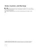
System Overview Figure 1. Inside View – 1 1. memory shield 2. system board shield 3. bottom cover 4. power-switch board 5. hard drive 6. VESA Bracket 7. optical drive 8.
Figure 2. Inside View – 2 1. WLAN card 2. memory module 3. power supply unit 4. system board 5. speaker 6. display bracket 7. system fan 8. heatsink 9. camera 10. microphone System Board Layout The following image displays the system board layout of the computer.
1. SD Memory card reader 2. memory module 3. speaker connector 4. touch connector 5. control board connector 6. HDD connector 7. ODD connector 8. SATA power connector 9. convertor board connector 10. power connector 2 11. power connector 1 12. system fan connector 13. processor connector 14. coin-cell Battery 15. WLAN connector 16. LVDS connector 17.
Removing and Installing Components 3 This section provides detailed information on how to remove or install the components from your computer. Removing the Stand 1. Follow the procedures in Before Working Inside Your Computer. 2. Remove the stand cover. 3. Remove the screws that secure the stand to the computer and remove the stand from the computer. Installing the Stand 1. Align the stand on the computer, and tighten the screws to secure the stand to the computer. 2.
3. Perform the following steps as shown in the illustration: a. Using a scribe, pry the edges of the computer [1]. b. Remove the back cover from the computer [2]. Installing the Back Cover 1. Place the back cover on the computer. 2. Press at the corners of the back cover to secure it to the computer. 3. Install: a. stand b. stand cover 4. Follow the procedures in After Working Inside Your Computer. Removing the Optical Drive 1. Follow the procedures in Before Working Inside Your Computer. 2.
3. Remove the screw that secures the optical drive to the computer . Slide the optical drive out of the computer. Installing the Optical Drive 1. Slide the optical drive to the computer and tighten the screw to secure it. 2. Install: a. back cover b. stand c. stand cover 3. Follow the procedures in After Working Inside Your Computer. Removing the Hard Drive 1. Follow the procedures in Before Working Inside Your Computer. 2. Remove: a. stand cover b. stand c.
3. Perform the following steps as shown in the illustration: a. Push the hard-drive bracket to release it from its lock [1]. b. Lift the hard drive from one edge [2]. 4. Slide and remove it to access the hard-drive cable. 5. Disconnect the hard-drive cable from the hard drive, and remove it from the computer.
6. Pry the hard-drive bracket apart to release the hard drive. Remove the hard drive from the hard-drive bracket. Installing the Hard Drive 1. Insert the hard drive into the hard-drive bracket. 2. Connect the hard-drive cable to the hard drive and align the hard drive to its slot on the computer. 3. Install: a. back cover b. stand c. stand cover 4. Follow the procedures in After Working Inside Your Computer. Removing the Convertor Board 1.
3. Disconnect the cables from the convertor board. Remove the screws and lift the convertor board from the computer. Installing the Convertor Board 1. Tighten the screws to secure the convertor board to the computer. Connect the cables to the convertor board. 2. Install: a. back cover b. stand c. stand cover 3. Follow the procedures in After Working Inside Your Computer. Removing the Memory 1. Follow the procedures in Before Working Inside Your Computer. 2. Remove: a. stand cover b. stand c.
3. Perform the following steps as shown in the illustration: a. Slide to release the memory cover from the computer [1]. b. Remove the memory cover from the computer [2]. 4. Pry the retention clips away from the memory module until it pops up. Lift and remove the memory module from its connector. Installing the Memory 1. Align the notch on the memory-card with the tab in the system-board connector. 2. Press down on the memory module until the release tabs spring back to secure them in place. 3.
3. Perform the following steps as shown in the illustration: a. Remove the screws that secure the system-board shield to the computer [1]. b. Lift the system-board shield from the computer [2]. c. Remove the system-board shield from the computer [3]. Installing the System-Board Shield 1. Align the system-board shield on the system board. Tighten the screws to secure it to the computer. 2. Install: a. back cover b. stand c. stand cover 3. Follow the procedures in After Working Inside Your Computer.
3. Perform the following steps as shown in the illustration:. a. Remove the screw that secure the heatsink to the computer [1]. b. Remove the screws that secure around CPU to the computer [2]. c. Lift and remove the heatsink from the computer [3]. Installing the Heatsink 1. Align the heatsink on the system board. Tighten the screws to secure it to the computer. 2. Install: a. b. c. d. 3. system-board shield back cover stand stand cover Follow the procedures in After Working Inside Your Computer.
3. Perform the following steps as shown in the illustration: a. Remove the screws that secure the speaker cover to the computer [1]. b. Release the speaker cover from the computer.[2]. 4. 20 Remove the speaker cover from the computer.
5. Perform the following steps as shown in the illustration: a. Disconnect the speaker cable from the system board [1]. b. Release the cable from the tabs on the computer [2]. 6. Perform the following steps as shown in the illustration: a. Remove the screws that secure the speakers to the computer [1]. b. Remove the speakers from the computer [2]. Installing the Speakers 1. Align the speakers on the computer. Tighten the screws to secure them to the computer. 2.
3. Align the speaker cover on the computer and tighten the screws to secure it. 4. Install: a. b. c. d. 5. system-board shield back cover stand stand cover Follow the procedures in After Working Inside Your Computer. Removing the VESA Bracket 1. Follow the procedures in Before Working Inside Your Computer. 2. Remove: a. stand cover b. stand c. back cover 3. Perform the following steps as shown in the illustration: a. Remove the screws that secure the VESA bracket to the computer [1]. b.
Removing the System Fan 1. Follow the procedures in Before Working Inside Your Computer. 2. Remove: a. b. c. d. e. 3. stand cover stand back cover System-board shield VESA bracket Perform the following steps as shown in the illustration: a. Disconnect the system-fan cable from the system board [1]. b. Remove the screws that secure the system fan [2]. c. Remove system fan from the computer [3]. Installing the System Fan 1.
Removing the Power-Switch Board 1. Follow the procedures in Before Working Inside Your Computer. 2. Remove: a. stand cover b. stand c. back cover 3. Peel the tape that secures the power-switch board to the computer. Lift the power-switch board to access the cable. 4. Disconnect the power-switch cable from the power-switch board to remove it from the computer.
Installing the Power-Switch Board 1. Insert the power-switch board into its slot on the computer and fix the tape to secure it. Connect the power-switch cable to the power-switch board. 2. Install: a. back cover b. stand c. stand cover 3. Follow the procedures in After Working Inside Your Computer. Removing the System Board 1. Follow the procedures in Before Working Inside Your Computer. 2. Remove: a. b. c. d. e. f. g. h.
3. Disconnect the following from the system board: a. camera cable b. LVDS cable c. system-fan cable d. optical-drive cable e. hard-drive cable f. hard-drive/optical-drive power cable g. convertor-board cable h. power-switch cable i. touch cable (if available) j. speaker cable 4. Perform the following steps as shown in the illustration: a. Remove the screws that secure the system board to the computer [1]. b. Slide the system board to release it from the computer [2].
5. Remove the system board from the computer. Installing the System Board 1. Align the system board on the computer. 2. Tighten the screws to secure the system board to the computer. 3. Connect the following cables to the system board: a. b. c. d. e. f. g. h. i. j. 4. Install: a. b. c. d. e. f. g. h. 5.
Removing the Display Bracket 1. Follow the procedures in Before Working Inside Your Computer. 2. Remove: a. b. c. d. e. f. g. h. i. j. k. l. m. n. 3. 28 stand cover stand back cover optical drive hard drive memory VESA bracket system-board shield speakers heatsink system fan WLAN card convertor board system board Release the LVDS, camera, convertor-board cables from their tabs on the display bracket.
4. Remove the screws that secure the display bracket to the computer. Lift and remove the display bracket from the computer. Installing the Display Bracket 1. Align the display bracket on the computer. 2. Tighten the screws to secure the display bracket to the computer. 3. Align the LVDS, camera, convertor-board cables through their tabs on the display bracket. 4. Install: a. b. c. d. e. f. g. h. i. j. k. l. m. n. 5.
Removing the Camera 1. Follow the procedures in Before Working Inside Your Computer. 2. Remove: a. b. c. d. e. f. g. h. i. j. k. l. m. n. o. 3. 30 stand cover stand back cover optical drive hard drive memory VESA bracket system-board shield speakers heatsink system fan WLAN card convertor board system board display bracket Remove the screws that secure the camera to the computer and release the camera from its slot to access the camera cable.
4. Disconnect the camera cable from the camera and remove the camera from the computer. Installing the Camera 1. Connect the camera cable to the camera. 2. Align the camera into its slot and tighten the screws to secure it to the computer. 3. Install: a. b. c. d. e. f. g. h. i. j. k. l. m. n. o. 4.
3. Perform the following steps as shown in the illustration: a. Remove the screw that secures the microphone. b. Disconnect the microphone cable from the microphone. c. Remove the microphone from the computer. Installing the Microphone 1. Connect the microphone cable to the microphone. 2. Align the microphone into its slot and tighten the screws to secure it to the computer. 3. Install: a. back cover b. stand c. stand cover 4. 32 Follow the procedures in After Working Inside Your Computer.
System Setup 4 System Setup enables you to manage your computer hardware and specify BIOS‐level options.
Table 1. Navigation Keys Keys Navigation Up arrow Moves to the previous field. Down arrow Moves to the next field. Allows you to select a value in the selected field (if applicable) or follow the link in the field. Spacebar Expands or collapses a drop‐down list, if applicable. Moves to the next focus area. NOTE: For the standard graphics browser only. Moves to the previous page till you view the main screen.
Option Description • Date/Time Enabled Legacy Options ROMs (Default: Enabled) Allows you to set the date and time. The changes to the system date and time takes effect immediately. Table 3. System Configuration Option Description Integrated NIC Allows you to configure the integrated network controller. The options are: • • • • • SATA Operation Allows you to configure the internal SATA harddrive controller.
Option Description Default Setting: All devices are enabled. Audio Allows you enable or disable the audio feature. • Enable Audio – Enable Microphone – Enable Internal Speaker Default Setting: All devices are enabled. OSD Button Management Allows you to disable the OSD (On-Screen Display) buttons. • Disable OSD Buttons Default Setting: OSD buttons are not disabled Miscellaneous Devices Allows you to enable or disable various on-board devices.
Option Description • Confirm the new password Strong Password Enable strong password - This option is disabled by default. Password Configuration This field controls the minimum and maximum number of characters allowed for the admin and system passwords. • • • • Admin Password Min Admin Password Max System Password Min System Password Max By default the minimum characters are set to 4 and maximum to 32.
Table 5. Secure Boot Option Description Secure Boot Enable Allows you to enable or disable the Secure Boot Feature. The options are: • • Expert Key Management Disabled (Default) Enabled Allows you to manipulate the security key databases only if the system is in Custom Mode. The Enable Custom Mode option is disabled by default. The options are: • • • • PK KEK db dbx If you enable the Custom Mode, the relevant options for PK, KEK, db, and dbx appear.
Option Description Limit CPUID Value This field limits the maximum value the processor Standard CPUID Function will support • Enable CPUID Limit (Disabled by default) NOTE: Some Operating system will not complete installation when the maximum CPUID Function is greater than 3 Intel TurboBoost Allows you to enable or disable Intel TurboBoost mode of the processor. This option is enabled by default.
Option Description • • • LAN Only WLAN only LAN with PXE Boot This option is Disabled by default. Block Sleep Allows you to block entering to sleep (S3 state) in OS Environment. • Intel Smart Connect Technology Block Sleep (S3 State) This option is disabled by default. The option is disabled by default. If option enables will periodically sense nearby wireless connection while the system is asleep.
Table 11. Maintenance Option Description Service Tag Displays the service tag of your computer. Asset Tag Allows you to create a system asset tag if an asset tag is not already set. This option is not set by default. SERR Messages Controls the SERR message mechanism. This option is enabled by default. Some graphics cards require that the SERR message mechanism be disabled. • Enable SERR Messages Table 12.
Option Description NOTE: This field is only relevant when the Integrated NIC control in the System Configuration group is set to Enabled with ImageServer and when Client DHCP is set to Static IP. Client SubnetMask Displays the subnet mask of the client. The default setting is 255.255.255.255. NOTE: This field is only relevant when the Integrated NIC control in the System Configuration group is set to Enabled with ImageServer and when Client DHCP is set to Static IP.
6. Select your computer model and the Product Support page of your computer appears. 7. Click Get drivers and click View All Drivers. The Drivers and Downloads page opens. 8. On the Drivers and Downloads screen, under the Operating System drop-down list, select BIOS. 9. Identify the latest BIOS file and click Download File. You can also analyze which drivers need an update. To do this for your product, click Analyze System for Updates and follow the instructions on the screen. 10.
3. Select System Password , enter your system password, and press or . Use the following guidelines to assign the system password: • A password can have up to 32 characters. • The password can contain the numbers 0 through 9. • Only lower case letters are valid, upper case letters are not allowed. • Only the following special characters are allowed: space, (”), (+), (,), (-), (.), (/), (;), ([), (\), (]), (`). Re-enter the system password when prompted. 4.
Technical Specifications 5 NOTE: Offerings may vary by region. The following specifications are only those required by law to ship with your computer. For more information about the configuration of your computer, go to Help and Support in your Windows operating system and select the option to view information about your computer. Table 14.
Feature Discrete Specification 1 GB DDR3 Table 17. Audio Feature Specification Controller ALC3661-CG (Realtek) Speaker single 4-ohms, 2 W AVG speakers with 2.5 W Peak Internal speaker amplifier up to 6 W per channel Internal microphone support single digital microphone Volume controls Volume up/down buttons (Windows 7 only), program menus, and keyboard media-control keys Table 18.
Table 21. Drives Feature Specification Hard drive one 2.5-inch SATA drive Optical drive (optional) one DVD-ROM, DVD+/- RW Table 22. Ports and Connectors Feature Specification Audio: one universal audio jack/Line-out port Network adapter one RJ45 connector USB 2.0 four connectors in the back panel USB 3.0 two connectors on the side panel Media card reader one 4-in-1 slot Table 23.
Table 24. Camera (optional) Feature Specification Image resolution 0.92 megapixel Video resolution 720p @ 30 FPS HD Diagonal viewing angle 74 degrees Table 25. Stand Feature Specification Tilt –5 degrees to 30 degrees Table 26. Physical Dimensions Feature Without Stand With Stand Width 489.92 mm (19.29 inches) 489.92 mm (19.29 inches) Height 328.84 mm (12.95 inches) 385.58 mm (15.18 inches) non-touch 67.62 mm (2.66 inches) 204.58 mm (8.05 inches) touch 66.72 mm (2.
Feature Specification Back panel: Link integrity light on integrated network adapter : Green — a good 10 Mbps connection exists between the network and the computer. Green— a good 100 Mbps connection exists between the network and the computer. Orange — a good 1000 Mbps connection exists between the network and the computer. Off (no light) — the computer is not detecting a physical connection to the network.
Contacting Dell 6 Contacting Dell NOTE: If you do not have an active Internet connection, you can find contact information on your purchase invoice, packing slip, bill, or Dell product catalog. Dell provides several online and telephone-based support and service options. Availability varies by country and product, and some services may not be available in your area. To contact Dell for sales, technical support, or customer service issues: 1. Visit dell.com/support 2. Select your support category. 3.