
Installation guide


4 Chapter 2
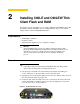
4. Lift the top cover to remove it and expose the main board as shown in Figure 3. Notice
that the rear of the thin client is positioned at the bottom of the photo.
Warning
Flash and RAM modules may be susceptible to damage by Electro-Static
Discharge (ESD). All industry-standard cautions should be followed to avoid
ESD. Before you remove or install a module, touch any metal part of the
chassis and keep that contact with the chassis during the installation
process.
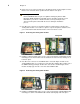
5. Note where the connector of the flash module is located in Figure 3. Remove the
existing flash module. Use needle-nose pliers to squeeze the plastic standoff lock as
you rock the flash module back and forth to remove it from the socket.
Figure 3 Removing the existing flash module
6. Install the new flash module in the reverse order of removing the original flash module.
Carefully press the flash module onto the standoff lock and connector, making sure to
lock it into place.
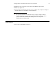
7. Note where the connector of the RAM module is located in Figure 4. Remove the
existing RAM module. Use your fingers to unlock the two retaining clips at either side of
the RAM module by pushing in the direction of the arrows shown in Figure 4. The
module should pop up from its socket. Lift out the RAM module.
Figure 4 Removing the existing flash module
8. Install the new RAM module in the reverse order of removing the original RAM module.
Carefully press down on the RAM module until its retaining clips lock it into place.