
Service Manual
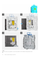
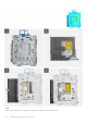
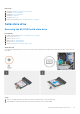
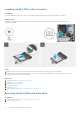
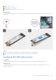
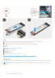

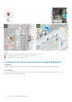
Table Of Contents
- OptiPlex 5000 Small Form Factor Service Manual
- Contents
- Working inside your computer
- Removing and installing components
- Recommended tools
- Screw list
- Customer Replaceable Units (CRU) and Field Replaceable Units (FRU) list
- Major components of OptiPlex 5000 Small Form Factor
- Side cover
- Front bezel
- Intrusion switch
- Hard drive
- Hard-drive and optical-drive bracket
- Optical drive
- Solid-state drive
- Hard-drive and optical-drive supporting bracket
- SD-card reader
- Coin-cell battery
- Power button
- WLAN card
- WLAN antenna
- WLAN antennas (External)
- Memory
- Processor fan and heat-sink assembly
- Voltage regulator heat sink
- Processor
- Expansion card
- Optional I/O modules (PS2/Serial)
- Optional I/O modules (VGA/HDMI/DP/USB Type-C)
- Chassis fan
- Speakers
- Power-supply unit
- System board
- Drivers and downloads
- Getting help and contacting Dell

Steps
1. Remove the two (#6-32) screws that secures the bracket to the chassis.
2. Push the bracket to free it from the front side of the chassis.
3. Lift and remove the bracket from the system.
Installing the hard-drive and optical-drive supporting bracket
Prerequisites
If you are replacing a component, remove the existing component before performing the installation procedure.
About this task
The following images indicate the location of the hard-drive and optical-drive supporting bracket and provides a visual
representation of the installation procedure.
40
Removing and installing components