
Service Manual
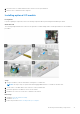
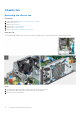
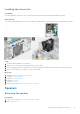
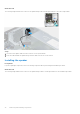
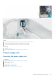
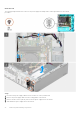
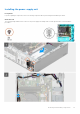
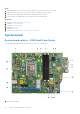
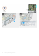
Table Of Contents
- OptiPlex 5000 Small Form Factor Service Manual
- Contents
- Working inside your computer
- Removing and installing components
- Recommended tools
- Screw list
- Customer Replaceable Units (CRU) and Field Replaceable Units (FRU) list
- Major components of OptiPlex 5000 Small Form Factor
- Side cover
- Front bezel
- Intrusion switch
- Hard drive
- Hard-drive and optical-drive bracket
- Optical drive
- Solid-state drive
- Hard-drive and optical-drive supporting bracket
- SD-card reader
- Coin-cell battery
- Power button
- WLAN card
- WLAN antenna
- WLAN antennas (External)
- Memory
- Processor fan and heat-sink assembly
- Voltage regulator heat sink
- Processor
- Expansion card
- Optional I/O modules (PS2/Serial)
- Optional I/O modules (VGA/HDMI/DP/USB Type-C)
- Chassis fan
- Speakers
- Power-supply unit
- System board
- Drivers and downloads
- Getting help and contacting Dell
2. Processor-power cable
3. Processor fan connector
4. UDIMM slots
From the left (a>b>c>d):
DIMM 3
DIMM 1
DIMM 4
DIMM 2
5. Coin-cell battery socket
6. Power-button cable
7. SD-card reader slot
8. M.2 WLAN slot
9. Hard-drive data cable (SATA 0)
10. System-power cable
11. Internal-speaker cable
12. Hard-drive data cable (SATA 1)
13. Optical-drive/hard-drive data cable (SATA 2)
14. SATA power cable
15. a. PCIe x16 slot (SLOT 2)
b. PCIe x4 slot (SLOT 4)
16. M.2 2230/2280 solid-state drive slot
17. Processor socket
18. I/O cable
Removing the system board
Prerequisites
1. Follow the procedure in before working inside your computer.
2. Remove the side cover.
3. Remove the front bezel.
4. Remove the 2.5-inch hard-drive.
5. Remove the 3.5-inch hard-drive.
6. Remove the hard-drive and optical-drive cage.
7. Remove the expansion card.
8. Remove the solid-state drive.
9. Remove the WLAN card.
10. Remove the heat-sink and fan assembly.
11. Remove the memory modules.
12. Remove the processor.
About this task
The following images indicate the location of the system board and provide a visual representation of the removal procedure.
Removing and installing components
79