Dell Latitude 12 Rugged Extreme — 7204 Owner's Manual Regulatory Model: P18T Regulatory Type: P18T001
Notes, Cautions, and Warnings NOTE: A NOTE indicates important information that helps you make better use of your computer. CAUTION: A CAUTION indicates either potential damage to hardware or loss of data and tells you how to avoid the problem. WARNING: A WARNING indicates a potential for property damage, personal injury, or death. Copyright © 2014 Dell Inc. All rights reserved. This product is protected by U.S. and international copyright and intellectual property laws.
Contents 1 Working on Your Computer................................................................................5 Before Working Inside Your Computer................................................................................................ 5 Turning Off Your Computer..................................................................................................................6 After Working Inside Your Computer......................................................................................
Installing the WLAN Card.................................................................................................................... 23 Removing the WWAN Card.................................................................................................................23 Installing the WWAN Card.................................................................................................................. 24 Removing the Global Positioning System (GPS) Module.....................................
Working on Your Computer 1 Before Working Inside Your Computer Use the following safety guidelines to help protect your computer from potential damage and to help to ensure your personal safety. Unless otherwise noted, each procedure included in this document assumes that the following conditions exist: • You have read the safety information that shipped with your computer. • A component can be replaced or -- if purchased separately/installed by performing the removal procedure in reverse order.
To avoid damaging your computer, perform the following steps before you begin working inside the computer. 1. Ensure that your work surface is flat and clean to prevent the computer cover from being scratched. 2. Turn off your computer (see Turning Off Your Computer). 3. If the computer is connected to a docking device (docked), undock it. CAUTION: To disconnect a network cable, first unplug the cable from your computer and then unplug the cable from the network device. 4.
2. Click Shut Down. or 2. 1. Click Start . 2. Click the arrow in the lower-right corner of the Start menu as shown below, and then click Shut Down . Ensure that the computer and all attached devices are turned off. If your computer and attached devices did not automatically turn off when you shut down your operating system, press and hold the power button for about 6 seconds to turn them off.
Removing and Installing Components 2 This section provides detailed information on how to remove or install the components from your computer. Removing the Stylus and Tether 1. Follow the procedures in Before Working Inside Your Computer 2. To remove stylus and tether: a. Pull the stylus out from it’s slot on the computer [1]. b. Release and remove the tether from the computer [2]. Installing the Stylus and Tether 1. Insert the tether into the slot on the computer 2.
WARNING: To prevent ignition in a hazardous atmosphere, batteries must only be changed or charged in an area known to be non-hazardous. 1. Follow the procedures in Before Working Inside Your Computer. 2. To remove the battery: a. Push the battery latch towards the back of the computer. b. Slide the latch to release the battery. c. Slide the battery out of the computer. Installing the Battery 1. Slide the battery into the battery bay. 2. Slide the latch to lock position. 3.
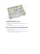
Installing the Bottom Cover 1. Place the bottom cover on the base of the computer. 2. Tighten the screws that secure the bottom cover to the computer chassis. 3. Install the battery. 4. Follow the procedures in After Working Inside Your computer. Removing the Keyboard and Keyboard door 1. Follow the procedures in Before Working Inside Your Computer. 2. To release the keyboard: a. Remove the screws that secure the keyboard to the computer chassis [1]. b.
3. To remove the keyboard door: a. Remove the screws that secure the keyboard door [1]. b. Lift the keyboard door [2]. c. Disconnect the keyboard cables from the motherboard connector by pressing on the locking tab and lifting the connector upwards [3,4]. d. Lift and remove the keyboard from the computer chassis. Installing the Keyboard and Keyboard Door 1. Connect the keyboard cables to its connectors on the keyboard controller card. 2. Place the keyboard door over its slot on the computer chassis.
Removing the Hard Drive 1. Follow the procedures in Before Working Inside Your Computer. 2. Remove battery 3. To remove the hard drive: a. Unlock the hard-drive press latch door and lift it upwards to open it [1,2]. b. Pull the tab to pull the hard drive out of the computer [3]. Installing the Hard Drive 1. Slide the hard drive into its place on the computer. 2. Close the hard-drive bay press latch door. 3. Install battery. 4. Follow the procedures in After Working Inside Your computer.
Installing the System Fan 1. Align the system fan in its position on the computer chassis. 2. Tighten the screws to secure the system fan to the computer chassis. 3. Connect the system fan connector cable to the system board connector. 4. Install: a. battery b. bottom cover 5. Follow the procedures in After Working Inside Your computer. Removing the Memory Module 1. Follow the procedures in Before Working Inside Your Computer. 2. Remove: a. battery b. bottom cover 3.
Installing the Memory Module 1. Insert the memory module into the memory socket. 2. Press the memory module down until it clicks into place. 3. Install: a. bottom cover b. battery 4. Follow the procedures in After Working Inside Your computer. Removing the MEMS Board MEMS board is also known as the sensor board. 1. Follow the procedures in Before Working Inside Your Computer. 2. Remove: a. battery b. bottom cover 3. To remove the MEMS board: a.
Installing the MEMS Board 1. Place the MEMS board in the slot. 2. Tighten the screws to secure the MEMS board. 3. Connect the cable to the MEMS board. 4. Install: a. bottom cover b. battery 5. Follow the procedures in After Working Inside Your computer. Removing the USH Board 1. Follow the procedures in Before Working Inside Your Computer. 2. Remove: a. battery b. bottom cover 3. To remove the USH board: a. b. c. d. e. Disconnect the USH board cables from the connectors [1,2].
Installing the USH Board 1. Connect the smart card cable to the USH board at the bottom of the board. 2. Flip the USH board to replace it to its original position. 3. Tighten the screws to secure the USH board. 4. Connect the cables to the USH board. 5. Install: a. bottom cover b. battery 6. Follow the procedures in After Working Inside Your computer. Removing the Docking Board 1. Follow the procedures in Before Working Inside Your Computer. 2. Remove: a. battery b. bottom cover 3.
4. To remove the docking board: a. Flip the board [1]. b. Disconnect the docking board connector cable from the system board by lifting the cablerelease tab [2]. c. Lift and remove the docking board from the computer chassis [3]. Installing the Docking Board 1. Connect the docking board connector cable to the system board. 2. Flip the docking board and seat it on the slot. 3. Tighten the screws to secure the docking board. 4. Connect the antenna cables to the docking board. 5. Install: a.
a. battery b. bottom cover 3. To remove heatsink: a. Loosen the screws that secure the heatsink to the system board in the sequence shown [1,2,3,4]. NOTE: The screws are retained by the heatsink and should not be fully removed. b. Lift and remove the heatsink from the computer chassis. Installing the Heatsink 1. Clean the old thermal grease and re-apply the grease at the base of the heatsink. 2. Align the heatsink to its position on the system board. 3.
Installing the Speaker 1. Place the speaker in the slot on the computer chassis. 2. Tighten the screws to secure the speaker. 3. Connect the speaker cable to the system board. 4. Install: a. bottom cover b. battery 5. Follow the procedures in After Working Inside Your Computer. Removing the SIM Board Assembly 1. Follow the procedures in Before Working Inside Your Computer. 2. Remove: a. battery b. bottom cover 3.
NOTE: To remove the SIM board from the assembly, remove the screws that secure the SIM board to the SIM bracket. Installing the SIM Board Assembly 1. Place the SIM board on the bracket and tighten the screws. 2. Place the SIM board assembly in the slot on the computer chassis. 3. Tighten the screws to secure the SIM board. 4. Connect the cable to the SIM board connector. 5. Connect the cable to the system board, if you had disconnected the SIM board cable from the system board. 6. Install: a.
Installing the Coin-Cell Battery 1. Connect the coin-cell battery to the system board connector. 2. Insert the coin-cell battery in the slot on the computer chassis. 3. Install: a. bottom cover b. battery 4. Follow the procedures in After Working Inside Your computer. Removing the Antenna Routing Bracket 1. Follow the procedures in Before Working Inside Your Computer. 2. Remove: a. battery b. bottom cover 3. Remove the tapes that secure the wireless antenna cables. 4.
Installing the Antenna Routing Bracket 1. Place the antenna routing bracket in the slot on the computer chassis. 2. Tighten the screws to secure the cable holder. 3. Route the antenna cables into the routing channels. 4. Connect all the wireless antenna cables to the connectors. 5. Secure the tapes to secure the wireless antenna cables. 6. Install: a. bottom cover b. battery 7. Follow the procedures in After Working Inside Your Computer. Removing the WLAN Card 1.
Installing the WLAN Card 1. Insert the WLAN card in the slot. 2. Connect the screw to secure the cable holder. 3. Connect the antenna cables to the WLAN card. 4. Install: a. antenna routing bracket b. bottom cover c. battery 5. Follow the procedures in After Working Inside Your Computer. Removing the WWAN Card 1. Follow the procedures in Before Working Inside Your Computer 2. Remove: a. battery b. bottom cover c. antenna routing bracket 3. To remove the WWAN card: a.
Installing the WWAN Card 1. Slide the WWAN card into its connector on the system board. 2. Press the card down and tighten the screw to secure the WWAN card. 3. Connect the antenna cables as per the color code, on the WWAN card. 4. Install: a. antenna routing bracket b. bottom cover c. battery 5. Follow the procedures in After Working Inside Your Computer. Removing the Global Positioning System (GPS) Module 1. Follow the procedures in Before Working Inside Your Computer. 2. Remove: a.
Installing the Global Positioning System (GPS) Module 1. Insert the GPS module into its slot and press down the latch to secure it. 2. Connect the cable to the connector on the GPS module. 3. Connect the antenna cable to the GPS module 4. Install: a. bottom cover b. battery 5. Follow the procedures in After Working Inside Your Computer. Removing the Card Bracket 1. Follow the procedures in Before Working Inside Your Computer. 2. Remove: a. b. c. d. e. f. g.
5. To unroute the cables: a. Unroute the GPS and the C-storage cables. b. Remove the screws that secure the card bracket to the computer chassis. 6. To remove the card bracket: a. Flip the card bracket [1]. b. Disconnect the camera cable from the connector [2]. c. Lift up and remove the card bracket [3].
Installing the Card Bracket 1. Place the card bracket in the slot on the computer chassis. 2. Connect the camera cable to the connector on the card bracket. 3. Flip the card bracket and seat the card on the slot. 4. Tighten the screws to secure the card bracket. 5. Route the GPS and the C-storage cable through the routing channels. 6. Connect the MEMS cables to the system board. 7. Connect the battery cable to the battery board connector and the system board. 8. Install: a. b. c. d. e. f. g.
Installing the I/O Board 1. Insert the I/O board in its slot. 2. Tighten the screws to secure the I/O board. 3. Connect the I/O board cable to the I/O board. 4. Install: a. b. c. d. e. f. g. h. i. 5. card bracket Connect the battery cable to the battery board. hard drive MEMS board USH board GPS module docking board bottom cover battery Follow the procedures in After Working Inside Your Computer. Removing the Fingerprint Reader 1. Follow the procedures in Before Working Inside Your Computer 2.
Installing the Fingerprint Reader 1. Place the fingerprint reader in the slot on the computer chassis. 2. Tighten the screws to secure the fingerprint reader. 3. Install: a. b. c. d. e. f. g. h. 4. card bracket hard drive MEMS board USH board GPS module docking board bottom cover battery Follow the procedures in After Working Inside Your computer. Removing the LED Board 1. Follow the procedures in Before Working Inside Your Computer. 2. Remove: a. b. c. d. e. f. g. h. i. 3.
d. Remove the screws that secure the LED board [5]. e. Lift the LED board from the computer chassis [6]. Installing the LED Board 1. Insert the LED board in the slot on the computer chassis. 2. Connect the screws to secure the LED board. 3. Push the LED board to secure it. 4. Connect the screws to secure the board. 5. Connect the LED board to the connector. 6. Install: a. b. c. d. e. f. g. h. i. 7.
f. MEMS board g. hard drive h. card bracket 3. Disconnect the battery cable from the battery board. 4. To remove the battery board: a. Remove the screws that secure the battery board [1] b. Disconnect the battery board from the connector [2]. c. Lift the battery board away from the computer [3]. Installing the Battery Board 1. Slide the battery board to its connector. 2. Tighten the screws to secure the battery board. 3. Connect the battery cable to the battery board. 4. Install: a. b. c. d. e.
f. g. h. i. j. k. l. m. n. o. p. q. r. 3. MEMS board hard drive Disconnect the battery cable from the battery board. system fan card bracket memory module antenna routing bracket WLAN WWAN heatsink battery board SIM board system board To remove the keyboard control board: a. Remove the screws that secure the keyboard control board [1]. b. Lift the keyboard control board from the computer chassis [2]. Installing the Keyboard Control Board 1.
l. m. n. o. p. q. r. 4. hard drive MEMS board USH board GPS module docking board bottom cover battery Follow the procedures in After Working Inside Your computer. Removing the Power Connector 1. Follow the procedures in Before Working Inside Your Computer 2. Remove: a. b. c. d. e. f. g. h. i. j. k. l. m. n. o. p. q. r. 3. battery bottom cover docking board GPS module USH board MEMS board hard drive Disconnect the battery cable from the battery board.
Installing the Power Connector 1. Insert the power connector by aligning it with the connector side with the base of the computer chassis. 2. Press to firmly secure the power connector to the computer chassis. 3. Install: a. b. c. d. e. f. g. h. i. j. k. l. m. n. o. p. q. r. 4. system board SIM board battery board heatsink WWAN WLAN antenna routing bracket memory card bracket system fan Connect the battery cable to the battery board.
r. system board 3. To release the palmrest: a. Remove the screws that secure the palmrest [1]. b. Flip the computer chassis [2]. 4. To remove the palmrest: a. Open the display [1]. b. Pry the palmrest from the retention hooks [2]. Installing the Palmrest 1. Align the palmrest and press it firmly. 2. Close the display and flip the computer chassis. 3. Tighten the screws to secure the palmrest to the computer chassis. 4. Install: a. system board b. SIM board c.
d. e. f. g. h. i. j. k. l. m. n. o. p. q. r. 5. heatsink WWAN WLAN antenna routing bracket memory card bracket system fan Connect the battery cable to the battery board. hard drive MEMS board USH board GPS module docking board bottom cover battery Follow the procedures in After Working Inside Your computer. Removing the Display Assembly 1. Follow the procedures in Before Working Inside Your Computer. 2. Remove: a. b. c. d. e. f. g. h. i. j. k. l. 3.
4. To release the display assembly: a. Remove the screws that secure the display hinge cover [1]. b. Lift and remove the display hinge cover [2]. c. Lift and pull the rubber gasket to release the cables routed through the gasket [3]. 5. Remove the screws that secure the display hinges and flip the computer chassis. 6. Unlock the display and lift the display to remove it from the computer chassis.
Installing the Display Assembly 1. Install the display assembly and close the display. 2. Flip the computer chassis. 3. Install the display hinges in their slots. 4. Tighten the screws to secure the hinges. 5. Route the cables through the rubber gasket. 6. Install the hinge cover. 7. Tighten the screws to secure the hinge cover. 8. Install the eDP connector and place the bracket in its slot. 9. Tighten the screws to secure the eDP connector to the system board. 10.
e. f. g. h. i. j. k. l. m. n. o. p. q. r. 3. GPS module USH board MEMS board hard drive system fan card bracket memory module antenna routing bracket WLAN WWAN heatsink battery board SIM board assembly keyboard Disconnect the following cables from the system board: a. I/O board cable b. speaker cable c. coin-cell battery cable 4. Disconnect the ribbon cables from the system board [1,2]. 5. To remove the video connectors: a. Open the connector latch door. b.
6. To remove the system board: a. b. c. d. Remove the screws that secure the eDP connector [1]. Lift and remove the eDP connector bracket [2]. Remove the screws that secure the system board [3]. Slide and lift the system board from the computer chassis [4]. Installing the System Board 1. Place the system board to align with the connectors. 2. Tighten the screws to secure the system board to the computer chassis. 3. Install the eDP connector and place the bracket in its slot. 4.
c. coin-cell battery cable 9. Install: a. b. c. d. e. f. g. h. i. j. k. l. m. n. o. p. q. keyboard SIM board assembly battery board heatsink WWAN WLAN antenna routing bracket memory module card bracket system fan hard drive MEMS board USH board GPS module dock board bottom cover battery 10. Follow the procedures in After Working Inside Your computer.
System Setup 3 System Setup enables you to manage your computer hardware and specify BIOS‐level options.
Table 1. Navigation Keys Keys Navigation Up arrow Moves to the previous field. Down arrow Moves to the next field. Allows you to select a value in the selected field (if applicable) or follow the link in the field. Spacebar Expands or collapses a drop‐down list, if applicable. Moves to the next focus area. NOTE: For the standard graphics browser only. Moves to the previous page till you view the main screen.
Option Description By default, all the options are checked. You can also deselect any option or change the boot order. Boot List Option Allows you to change the boot list option. • • Legacy UEFI Advanced Boot Options This option allows you the legacy option ROMs to load. By default, the Enable Legacy Option ROMs is checked. Date/Time Allows you to change the date and time. Table 3. System Configuration Option Description Integrated NIC Allows you to configure the integrated network controller.
Option Description Drives Allows you to configure the SATA drives on board. All drives are enabled by default. The options are: • • • • SMART Reporting This field controls whether hard drive errors for integrated drives are reported during system startup. This technology is part of the SMART (Self Monitoring Analysis and Reporting Technology) specification. This option is disabled by default.
Option Description Touchscreen This field controls whether the touchscreen is enabled or disabled. This option is enabled by default. Stealth Mode Control This field is used to enable or disable the stealth mode. This option is enabled by default.
Option Description Default Setting: Not set Strong Password Allows you to enforce the option to always set strong passwords. Default Setting: Enable Strong Password is not selected. NOTE: If Strong Password is enabled, Admin and System passwords must contain at least one uppercase character, one lowercase character and be at least 8 characters long. Password Configuration Allows you to determine the minimum and maximum length of Administrator and System passwords.
Option Description Default Setting: Enable Admin Setup Lockout Allows you to prevent users from entering Setup when an Administrator password is set. Default Setting: Enable Admin Setup Lockout is not selected. Table 6. Secure Boot Option Description Secure Boot Enable This option enables or disables the Secure Boot Feature. • • Expert Key Management Disable (default) Enable Allows you to manipulate the security key databases only if the system is in Custom Mode.
Option Description Default Setting: All Intel SpeedStep Allows you to enable or disable the Intel SpeedStep feature. Default Setting: Enable Intel SpeedStep C States Control Allows you to enable or disable the additional processor sleep states. Default Setting: The option C states is enabled. Intel TurboBoost Allows you to enable or disable the Intel TurboBoost mode of the processor.
Option Description • • • Wake on LAN/WLAN Allows you to enable or disable the feature that powers on the computer from the Off state when triggered by a LAN signal. • • • • • Block Sleep Control WLAN Radio Control WWAN Radio Control WLAN radio or Control WWAN radio is not selected (default) Disabled: This option is enabled by default LAN Only WLAN Only LAN or WLAN LAN with PXE Boot This option lets you block entering to sleep (S3 state) in Operating System environment.
Option Description Intel Smart Connect Technology This option, if enabled, periodically senses the nearby wireless connections, while the system is in sleep state. You can use this option to synchronize the email or other social media application that are open, when the system enters the sleep state. Table 9. POST Behavior Option Description Adapter Warnings Allows you to enable or disable the system setup (BIOS) warning messages when you use certain power adapters.
Table 10. Virtualization Support Option Description Virtualization Allows you to enable or disable the Intel Virtualization Technology. Enable Intel Virtualization Technology (default) VT for Direct I/O Enables or disables the Virtual Machine Monitor (VMM) from utilizing the additional hardware capabilities provided by Intel® Virtualization technology for direct I/O. Enable VT for Direct I/O — enabled by default.
Table 13. System Logs Option Description BIOS Events Allows you to view and clear the System Setup (BIOS) POST events. Thermal Events Allows you to view and clear the System Setup (Thermal) events. Power Events Allows you to view and clear the System Setup (Power) events. Updating the BIOS It is recommended to update your BIOS (system setup), on replacing the system board or if an update is available. For laptops, ensure that your computer battery is fully charged and connected to a power outlet 1.
CAUTION: The password features provide a basic level of security for the data on your computer. CAUTION: Anyone can access the data stored on your computer if it is not locked and left unattended. NOTE: Your computer is shipped with the system and setup password feature disabled. Assigning a System Password and Setup Password You can assign a new System Password and/or Setup Password or change an existing System Password and/or Setup Password only when Password Status is Unlocked.
NOTE: If you change the System and/or Setup password, re-enter the new password when promoted. If you delete the System and/or Setup password, confirm the deletion when promoted. 5. Press and a message prompts you to save the changes. 6. Press to save the changes and exit from the System Setup. The computer reboots.
Diagnostics 4 If you experience a problem with your computer, run the ePSA diagnostics before contacting Dell for technical assistance. The purpose of running diagnostics is to test your computer's hardware without requiring additional equipment or risking data loss. If you are unable to fix the problem yourself, service and support personnel can use the diagnostics results to help you solve the problem.
Device Status Lights Icon Description Turns on when you turn on the computer and blinks when the computer is in a power management mode. Turns on when the computer reads or writes data. Turns on steadily or blinks to indicate battery charge status. Turns on when wireless networking is enabled.
Contacting Dell 5 NOTE: If you do not have an active Internet connection, you can find contact information on your purchase invoice, packing slip, bill, or Dell product catalog. Dell provides several online and telephone-based support and service options. Availability varies by country and product, and some services may not be available in your area. To contact Dell for sales, technical support, or customer service issues: 1. Visit dell.com/support 2. Select your support category. 3.