Dell Latitude E7240 Owner's Manual Regulatory Model: P22S Regulatory Type: P22S001
Notes, Cautions, and Warnings NOTE: A NOTE indicates important information that helps you make better use of your computer. CAUTION: A CAUTION indicates either potential damage to hardware or loss of data and tells you how to avoid the problem. WARNING: A WARNING indicates a potential for property damage, personal injury, or death. © 2013 Dell Inc. All Rights Reserved.
Contents 1 Working on Your Computer....................................................................................................... 5 Before Working Inside Your Computer.....................................................................................................................5 Turning Off Your Computer....................................................................................................................................... 6 After Working Inside Your Computer....................
Installing the Speakers........................................................................................................................................... 23 Removing the Display-Hinge Cover........................................................................................................................ 23 Installing the Display-Hinge Cover......................................................................................................................... 24 Removing the Heatsink..........
Working on Your Computer 1 Before Working Inside Your Computer Use the following safety guidelines to help protect your computer from potential damage and to help to ensure your personal safety. Unless otherwise noted, each procedure included in this document assumes that the following conditions exist: • You have read the safety information that shipped with your computer. • A component can be replaced or--if purchased separately--installed by performing the removal procedure in reverse order.
NOTE: To avoid damaging the system board, you must remove the main battery before you service the computer. 7. Remove the main battery. 8. Turn the computer top-side up. 9. Open the display. 10. Press the power button to ground the system board. CAUTION: To guard against electrical shock, always unplug your computer from the electrical outlet before opening the display.
After Working Inside Your Computer After you complete any replacement procedure, ensure you connect any external devices, cards, and cables before turning on your computer. CAUTION: To avoid damage to the computer, use only the battery designed for this particular Dell computer. Do not use batteries designed for other Dell computers. 1. Connect any external devices, such as a port replicator or media base, and replace any cards, such as an ExpressCard. 2.
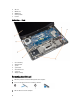
Removing and Installing Components 2 This section provides detailed information on how to remove or install the components from your computer. Recommended Tools The procedures in this document may require the following tools: • Small flat-blade screwdriver • Phillips screwdriver • Small plastic scribe System Overview Inside View — Back 1. 2. 3.
4. 5. 6. 7. 8. SD card WLAN card WWAN card memory module heatsink Inside view — Front 1. 2. 3. 4. 5. 6. 7. coin-cell battery SIM card board speaker system board wi-fi switch board system fan display assembly Removing the SD Card 1. Follow the procedures in Before Working Inside Your Computer. 2. Press in on the SD card to release it from the computer. 3. Slide the SD card out of the computer.
Installing the SD Card 1. Slide the SD card into its slot until it clicks into place. 2. Follow the procedures in After Working Inside Your Computer. Removing the Battery 1. Follow the procedures in Before Working Inside Your Computer. 2. Slide the release latch to unlock the battery. 3. Lift the battery from the computer.
Installing the Battery 1. Slide the battery into its slot until it clicks into place. 2. Follow the procedures in After Working Inside Your Computer. Removing the Base Cover 1. Follow the procedures in Before Working Inside Your Computer. 2. Remove battery. 3. Remove the screws that secure the base cover to the computer.
4. Lift the base cover to remove it from the computer.
Installing the Base Cover 1. Place the base cover to align with the screw holes correctly on the computer. 2. Tighten the screws to secure the base cover to the computer. 3. Install battery. 4. Follow the procedures in After Working Inside Your Computer. Removing the mSATA SSD Card 1. Follow the procedures in Before Working Inside Your Computer. 2. Remove: a) battery b) SD card c) base cover 3. Remove the screw that secures the mSATA SSD card and remove the mSATA SSD card from the computer.
Installing the Keyboard Trim 1. Align the keyboard trim to its slot. 2. Press along the sides of the keyboard trim until it clicks in place. 3. Install battery. 4. Follow the procedures in After Working Inside Your Computer. Removing the Keyboard 1. Follow the procedures in Before Working Inside Your Computer. 2. Remove: a) battery b) base cover c) keyboard trim 3. Lift the battery bay and remove the screw that secures the keyboard to the computer. 4.
Installing the Keyboard 1. Connect the keyboard cable and tighten the screw that secures the keyboard to the computer. 2. Slide the keyboard into its compartment and ensure that it clicks into place. 3. Flip the computer, place the keyboard, and tighten the screws that secure the keyboard to the computer. 4. Install: a) keyboard trim b) base cover c) battery 5. Follow the procedures in After Working Inside Your Computer. Removing the Palmrest 1.
5. Remove the screws that secure the palmrest assembly to the front of the computer. Pry the edges and lift the palmrest assembly from the computer. Installing the Palmrest 1. Align the palm rest assembly to its original position in the computer and snap it into place. 2. Tighten the screws to secure the palmrest assembly to the front of the computer. 3. Route the touch cable and connect to the system board. 4. Tighten the screws that secure the palmrest assembly to the base of the computer. 5.
d) keyboard trim e) keyboard f) palmrest 3. Disconnect the wi-fi switch board cable from the system board and remove the screw that secures the wi-fi swtich board to the computer. Remove the wi-fi switch board. Installing the Wi‐Fi Switch Board 1. Insert the wi-fi switch board in its slot. 2. Connect the wi-fi switch board to the system board. 3. Tighten the screw that secures the wi-fi switch board to the system board. 4. Install: a) b) c) d) e) f) 5.
Installing the Memory Module 1. Insert the memory module into the socket. 2. Press the retention clips to secure the memory module to the system board. 3. Install: a) base cover b) battery 4. Follow the procedures in After Working Inside Your Computer. Removing the WLAN Card 1. Follow the procedures in Before Working Inside Your Computer. 2. Remove: a) battery b) base cover 3. Disconnect the antenna cables from the WLAN card and remove the screw that secures the WLAN card to the computer.
c) base cover 3. Disconnect the antenna cables from the WWAN card. 4. Remove the screw that secures the WWAN card to the computer. 5. Disconnect the antenna cables from the WWAN card. Remove the screw that secures the WWAN card to the computer and remove it. Installing the WWAN Card 1. Place the WWAN card in its slot in the system board. 2. Press the WWAN card down and tighten the screw to secure the WWAN card to the computer. 3.
3. Install the battery 4. Follow the procedures in After Working Inside Your Computer. Removing the Display Panel 1. Follow the procedures in Before Working Inside Your Computer. 2. Remove: a) battery b) display bezel 3. Remove the screws that secure the display panel to the display assembly. Lift the display panel over. 4. Perform the following steps as shown in the illustration: a) Peel the LVDS cable connector tape [1]. b) Disconnect the LVDS cable from the display panel [2].
5. Follow the procedures in After Working Inside Your Computer. Removing the Coin-Cell Battery 1. Follow the procedures in Before Working Inside Your Computer. 2. Remove: a) b) c) d) e) f) SD card battery base cover keyboard trim keyboard palmrest 3. Remove the screw that secures the coin-cell battery to the system board. 4. Perform the following steps as shown in the illustration: a) Lift the latch that secures I/O cable to the computer [1]. b) Disconnect the I/O cable from the system board [2].
Removing the Speakers 1. Follow the procedures in Before Working Inside Your Computer. 2. Remove: a) b) c) d) e) f) 3. SD card battery base cover keyboard trim keyboard palmrest Perform the following steps as shown in the illustration: a) b) c) d) Disconnect the speaker cable [1]. Remove the screws that secure the speakers to the computer. Unroute the speaker cable from the system board [2]. Remove the speakers from the computer. Installing the Speakers 1.
Installing the Display-Hinge Cover 1. Place the display-hinge cover and tighten the screws to secure the display-hinge cover to the computer. 2. Install battery. 3. Follow the procedures in After Working Inside Your Computer. Removing the Heatsink 1. Follow the procedures in Before Working Inside Your Computer. 2. Remove: a) b) c) d) e) f) g) h) i) SD card battery base cover mSATA keyboard trim keyboard palmrest display-hinge cover display assembly 3.
Installing the Heatsink 1. Place the heatsink into its original position on the computer. 2. Tighten the screws to secure the heatsink to the computer. 3. Install: a) b) c) d) e) f) g) h) i) 4. display assembly display-hinge cover palmrest keyboard keyboard trim mSATA base cover battery SD card Follow the procedures in After Working Inside Your Computer. Removing the Display Assembly 1. Follow the procedures in Before Working Inside Your Computer. 2. Remove: a) b) c) d) e) 3.
5. Remove the screws that secure the display assembly to the computer and lift the display assembly from the computer. Installing the Display Assembly 1. Insert the LVDS and wireless antenna cables through the holes on the base chassis and connect them. 2. Place the display assembly onto the computer. 3. Tighten the screws on both sides to secure the display assembly. 4. Tighten the screw that secures heatsink to the computer. 5. Route and connect the LVDS cables through the routing channel. 6.
b) c) d) e) f) g) 3. SD card base cover keyboard trim keyboard palmrest display-hinge cover Remove the screws that secure the system fan to the computer and lift the system fan. Disconnect the system fan cable and lift the fan from the computer. Installing the System Fan 1. Connect the system-fan cable to the system board. 2. Tighten the screws that secure the system fan to the computer. 3. Align the system fan in its place on the system board. 4. Install: a) b) c) d) e) f) g) 5.
i) j) k) l) m) 3. Perform the following steps as shown in the illustration: a) b) c) d) e) 4. display-hinge cover display assembly system fan heat sink I/O cable Lift the I/O latch [1]. Remove the I/O cable from the system board [2]. Disconnect the I/O cable from system board[3]. Disconnect the speaker cable from the system board. Remove the screws that secure the system board to the computer.
b) c) d) e) f) g) h) i) j) k) l) 5. heat sink display assembly display-hinge cover speaker palmrest keyboard keyboard trim mSATA base cover battery SD card Follow the procedures in After Working Inside Your Computer. Removing the Power Connector 1. Follow the procedures in Before Working Inside Your Computer. 2. Remove: a) b) c) d) e) f) 3.
e) battery f) SD card 5. 30 Follow the procedures in After Working Inside Your Computer.
Docking Port Information 3 The docking port is used for connecting the laptop to a docking station (optional). 1.
System Setup 4 Boot Sequence Boot Sequence allows you to bypass the System Setup‐defined boot device order and boot directly to a specific device (for example: optical drive or hard drive). During the Power-on Self Test (POST), when the Dell logo appears, you can: • Access System Setup by pressing key • Bring up the one-time boot menu by pressing key The one-time boot menu displays the devices that you can boot from including the diagnostic option.
Keys Navigation Displays the System Setup help file. System Setup Options NOTE: Depending on your computer and its installed devices, the items listed in this section may or may not appear. Table 2. General Option Description System Information This section lists the primary hardware features of your computer. • • • • System Information: Displays BIOS Version, Service Tag, Asset Tag, Ownership Tag, Ownership Date, Manufacture Date, and the Express Service Code.
Option Description Date/Time Allows you to set the date and time. Table 3. System Configuration Option Description Integrated NIC Allows you to configure the integrated network controller. The options are: • • • • Parallel Port Allows you to define and set how the parallel port on the docking station operates. You can set the parallel port to: • • • • Serial Port Disabled Enabled Enabled w/PXE: This option is enabled by default.
Option Description • SATA-3 Default Setting: All drives are enabled. SMART Reporting This field controls if the hard drive errors for the integrated drives are reported during system startup. This technology is part of the SMART (Self Monitoring Analysis and Reporting Technology) specification. • USB Configuration Enable SMART Reporting - This option is disabled by default. Allows you to define the USB configuration. The options are: • • • Enable Boot Support Enable External USB Port Enable USB3.
Option Description • • Enable Media Card Disable Media Card Default Setting: All devices are enabled Table 4. Video Option Description LCD Brightness Allows you to set the display brightness depending up on the power source (On Battery and On AC). Table 5. Security Option Description Admin Password This field lets you set, change, or delete the administrator (admin) password (sometimes called the setup password). The admin password enables several security features.
Option Description Non-Admin Setup Changes Allows you to determine whether changes to setup option are permitted when an administrator password is set. The option is disabled. • Allows Wireless Switch Changes TPM Security Allows you to enable the Trusted Platform Module (TPM) during POST. Default Setting: The option is disabled.
• • • • • Replace from File- Replaces the current key with a key from a user-selected file Append from File- Adds a key to the current database from a user-selected file Delete- Deletes the selected key Reset All Keys- Resets to default setting Delete All Keys- Deletes all the keys NOTE: If you disable the Custom Mode, all the changes made will be erased and the keys will restore to default settings. Table 7.
Table 8. Power Management Option Description AC Behavior Allows the computer to power-on automatically, when AC adapter is plugged. The option is disabled. • Auto On Time Allows you to set the time at which the computer must turn on automatically. The options are: • • • • USB Wake Support Disabled (Default Setting) Every Day Weekdays Select Days Allows you to enable the USB devices to wake the computer from standby mode.
Option Description Primary Battery Configuration Allows you to define how to use the battery charge, when AC is plugged in. The options are: • • • • • Intel Smart Connect Technology Adaptive(Enabled) Standard Charge Express Charge Primary AC Use Custom Charge — you can set the percentage to which the battery must charge. The option is disabled by default. If option enables will periodically sense nearby wireless connection while the system is asleep.
Option Description • Extended BIOS POST Time Auto Allows to creates an additional pre-boot delay and allows the user to see POST status message. • • • 0 seconds 5 seconds 10 seconds Table 10. Virtualization Support Option Description Virtualization Allows you to enable or disable the Intel Virtualization Technology.
Table 12. Maintenance Option Description Service Tag Displays the service tag of your computer. Asset Tag Allows you to create a system asset tag if an asset tag is not already set. This option is not set by default. Table 13. System Logs Option Description BIOS events Displays the system event log and allows you to clear the log. • Thermal Events Displays the thermal event log and allows you to clear the log.
System and Setup Password You can create a system password and a setup password to secure your computer. Password Type Description System password Password that you must enter to log on to your system. Setup password Password that you must enter to access and make changes to the BIOS settings of your computer. CAUTION: The password features provide a basic level of security for the data on your computer.
Deleting or Changing an Existing System and/or Setup Password Ensure that the Password Status is Unlocked (in the System Setup) before attempting to delete or change the existing System and/or Setup password. You cannot delete or change an existing System or Setup password, if the Password Status is Locked. To enter the System Setup, press immediately after a power-on or reboot. 1. In the System BIOS or System Setup screen, select System Security and press .
Diagnostics 5 If you experience a problem with your computer, run the ePSA diagnostics before contacting Dell for technical assistance. The purpose of running diagnostics is to test your computer's hardware without requiring additional equipment or risking data loss. If you are unable to fix the problem yourself, service and support personnel can use the diagnostics results to help you solve the problem.
Turns on steadily or blinks to indicate battery charge status. Turns on when wireless networking is enabled. The device status LEDs are usually located either on the top or left side of the keyboard. They are used to display the storage, battery and wireless devices connectivity and activity. Apart from that they can be useful as a diagnostic tool when there's a possible failure to the system. The following table lists how to read the LED codes when possible errors occur. Table 15.
6 Specifications NOTE: Offerings may vary by region. The following specifications are only those required by law to ship with your computer. For comprehensive specification of your computer go to Specifications’ section in your Owner’s Manual available on the support site at dell.com/support. For more information about the configuration of your computer, go to Help and Support in your Windows operating system and select the option to view information about your computer. Table 16.
Feature Specification Stereo conversion 24-bit (analog-to-digital and digital-to-analog) Interface: Internal high-definition audio External microphone-in, stereo headphones, and headset combo connector Speakers two Internal speaker amplifier 1 W (RMS) per channel Volume controls hot keys Table 20.
Table 23. Ports and Connectors Features Specification Audio one microphone/stereo headphone/speakers connector Video Mini DisplayPort connector and 19-pin HDMI connector Network adapter RJ-45 connector USB 3.0 two USB 3.0 compliant connectors and one eSATA/USB 3.0 compliant connector Memory card reader Support upto SD4.0 Micro Subscriber Identity Module (uSIM) card one Docking port one Table 24.
Feature Y-axis Specification Latitude 7240 Latitude 7440 60.8 mm 47 mm Table 27. Battery Feature Specification Type • • Dimensions: Latitude 7240 Latitude 7440 Depth 80.75 mm (3.18 inches) 74.75 mm (2.94 inches) Height 7.20 mm (0.28 inch) 8.00 mm (0.31 inch) Width 282.00 mm (11.10 inches) 308.50 mm (12.15 inches) 3-cell 250.00 g (0.55 lb) 247.00 g (0.54 lb) 4–cell 300.00 g (0.66 lb) 308.00 g (0.
Feature Specification Dimensions 0.87 x 2.60 x 4.17 inches (22 x 66 x 106 mm) Temperature range: Operating 0 °C to 40 °C (32 °F to 104 °F) Non-Operating –40 °C to 70 °C (–40 °F to 158 °F) Table 29. Physical Feature Latitude 7240 Latitude 7440 Height 20.0 mm (0.79 inch) 21.0 mm (0.80 inch) Width 310.5 mm (12.22 inches) 337 mm (13.2 inches) Depth 211.0 mm (8.3 inches) 231.5 mm (9.1 inches) Weight (with 3cell battery) 1.36 kg (2.99 lb) 1.63 kg (3.6 lb) Table 30.
Contacting Dell 7 NOTE: If you do not have an active Internet connection, you can find contact information on your purchase invoice, packing slip, bill, or Dell product catalog. Dell provides several online and telephone-based support and service options. Availability varies by country and product, and some services may not be available in your area. To contact Dell for sales, technical support, or customer service issues: 1. Go to dell.com/contactdell. 2.