Dell Latitude E5450 / 5450 Owner's Manual Regulatory Model: P48G Regulatory Type: P48G001
Notes, Cautions, and Warnings NOTE: A NOTE indicates important information that helps you make better use of your computer. CAUTION: A CAUTION indicates either potential damage to hardware or loss of data and tells you how to avoid the problem. WARNING: A WARNING indicates a potential for property damage, personal injury, or death. Copyright © 2014 Dell Inc. All rights reserved. This product is protected by U.S. and international copyright and intellectual property laws.
Working on Your Computer 1 Before Working Inside Your Computer Use the following safety guidelines to help protect your computer from potential damage and to help to ensure your personal safety. Unless otherwise noted, each procedure included in this document assumes that the following conditions exist: • You have read the safety information that shipped with your computer. • A component can be replaced or--if purchased separately--installed by performing the removal procedure in reverse order.
3. If the computer is connected to a docking device (docked), undock it. CAUTION: To disconnect a network cable, first unplug the cable from your computer and then unplug the cable from the network device. 4. Disconnect all network cables from the computer. 5. Disconnect your computer and all attached devices from their electrical outlets. 6. Close the display and turn the computer upside-down on a flat work surface.
Or * On the Home screen, touch the and then select Shut down. – Using a mouse: a. Point to upper-right corner of the screen and click Settings. b. Click the and select Shut down. Or * • On the Home screen, click and then select Shut down. In Windows 7: 1. Click Start 2. Click Shut Down. . or 2. 1. Click Start . 2. Click the arrow in the lower-right corner of the Start menu as shown below, and then click Shut Down . Ensure that the computer and all attached devices are turned off.
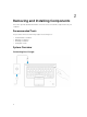
Removing and Installing Components This section provides detailed information on how to remove or install the components from your computer.
Front and Back View 1. network connector 2. VGA connector 3. USB 3.0 connectors 4. microphones (optional) 5. camera 6. camera-status light 7. HDMI connector 8. power connector 9. microphone 10. power button 11. USB 3.0 connector with PowerShare 12. memory-card reader 13. contactless smart-card reader (optional) 14.
15. wireless-status light 16. battery-status light 17. hard-drive activity light 18. power-status light 19. speakers 20. touchpad 21. smart-card reader (optional) 22. headset connector 23. security-cable slot 24. dock connector (optional) 25. Service-Tag label Removing the SD Card 1. Follow the procedures in Before Working Inside Your Computer. 2. Press in on the SD card to release it from the computer. 3. Slide the SD card out of the computer. Installing the SD Card 1.
NOTE: You may need a sharp tool to pry the base cover from its edge. Installing the Base Cover 1. Place the base cover to align with the screw holders on the computer. 2. Tighten the screws to secure the base cover to the computer. 3. Follow the procedures in After Working Inside Your Computer. Removing the Battery 1. Follow the procedures in Before Working Inside Your Computer. 2. Remove the base cover. 3.
a. Remove the screws that secure the battery to the computer [1]. b. Lift and push to remove the battery from the computer [2] [3]. Installing the Battery 1. Insert the battery into its place on the computer. 2. Route the battery cable through its routing channel. 3. Tighten the screws to secure the battery to the computer. 4. Connect the battery cable to its connector on the system board. 5. Install the base cover. 6. Follow the procedures in After Working Inside Your Computer.
4. Remove the hard-drive assembly from the computer. 5. Pull to release the hard-drive cable from its connector.
6. Remove the screws that secure the hard-drive bracket to the hard drive [1] and remove the hard drive from the hard-drive bracket [2]. Installing the Hard-Drive Assembly 1. Place the hard-drive bracket on the hard drive to align the screw holders and tighten the screws to secure the hard-drive bracket. 2. Connect the hard-drive cable to its connector on the hard drive. 3. Place the hard-drive assembly into its slot on the computer. 4.
a. battery b. base cover 7. Follow the procedures in After Working Inside Your Computer. Removing the Memory 1. Follow the procedures in Before Working Inside Your Computer. 2. Remove the: a. base cover b. battery 3. Pry the clips securing the memory module until the memory pops-up and remove the memory from the system board. Installing the Memory 1. Insert the memory on the memory socket until the clips secure the memory. 2. Install the: a. battery b. base cover 3.
NOTE: You may need a sharp tool to pry the keyboard trim from its edges. 3. Remove the keyboard trim from the keyboard. Installing the Keyboard Trim 1. Insert the keyboard trim to the keyboard until it snaps in its place. 2. Follow the procedures in After Working Inside Your Computer. Removing the Keyboard 1. Follow the procedures in Before Working Inside Your Computer. 2. Remove the: a. base cover b. battery c. keyboard trim 3.
5. Remove the keyboard from the computer. Installing the Keyboard 1. Place the keyboard to align with the screw holders on the computer. 2. Connect the keyboard cable and touchpad cables to their connectors on the system board. 3. Tighten the screws to secure the keyboard to the computer. 4. Install the: a. keyboard trim b. battery c. base cover 5. Follow the procedures in After Working Inside Your Computer. Removing the Palmrest 1. Follow the procedures in Before Working Inside Your Computer.
a. b. c. d. base cover battery keyboard trim keyboard 3. Remove the screws that secure the palmrest to the computer. 4. Flip the computer and perform the following steps: a. Disconnect the following cables from its connectors on the system board [1] [2]: • LED board • touchpad board • USH board b. Pry the palmrest on its edges to release it from the computer [3] 5. 16 Remove the palmrest from the computer.
Installing the Palmrest 1. 2. Place the palmrest on the computer. Connect the following cables to their connectors on the system board: a. LED board b. USH board c. touchpad board 3. Tighten the screws to secure the palmrest to the computer. 4. Install the: a. b. c. d. 5. keyboard keyboard trim battery base cover Follow the procedures in After Working Inside Your Computer Removing the SmartCard Reader Board 1. 2. Follow the procedures in Before Working Inside Your Computer. Remove the: a. b. c. d.
4. Release the SmartCard reader board. To release the SmartCard reader board: a. Remove the screws that secure the SmartCard-reader board to the palmrest [1]. b. Push the SmartCard-reader board to release it [2]. 5. 18 Remove the SmartCard reader board from the palmrest.
Installing the SmartCard-Reader Board 1. Place the SmartCard-reader board into its slot on the palmrest. 2. Tighten the screws to secure the SmartCard-reader board to the palmrest. 3. Fix the SmartCard-reader cable and connect the SmartCard-reader cable to its connector on the USH board. 4. Install the: a. b. c. d. e. 5. palmrest keyboard keyboard trim battery base cover Follow the procedures in After Working Inside Your Computer. Removing the USH Board 1.
Installing the USH Board 1. Place the USH Board on the palmrest. 2. Tighten the screw to secure the USH board to the palmrest. 3. Connect all the cables to the USH board. 4. Install the: a. b. c. d. e. f. 5. palmrest keyboard keyboard trim hard-drive assembly battery base cover Follow the procedures in After Working Inside Your Computer. Removing the Finger-Print Reader Board 1. Follow the procedures in Before Working Inside Your Computer. 2. Remove the: a. b. c. d. e. 3.
Installing the Finger-Print Reader Board 1. Insert the finger-print reader board into its place on the palmrest. 2. Connect the finger-print reader cable to the finger-print reader board. 3. Place the metal bracket on the finger-print reader board and tighten the screw to secure the fingerprint reader board. 4. Install the: a. b. c. d. e. 5. keyboard trim keyboard palmrest battery base cover Follow the procedures in After Working Inside Your Computer. Removing the LED Board 1.
Installing the LED Board 1. Insert the LED board into its slot on the palmrest. 2. Tighten the screw that secures the LED board to the palmrest. 3. Connect the LED-board cable to its connector on the LED board. 4. Install the: a. b. c. d. e. 5. palmrest keyboard keyboard trim battery base cover Follow the procedures in After Working Inside Your Computer. Removing the Power-Connector Port 1. Follow the procedures in Before Working Inside Your Computer. 2. Remove the: a. base cover b.
4. Disconnect the power-connector port cable from its connector [1] and remove the powerconnector port from the computer [2]. Installing the power-connector port 1. Insert the power-connector port into its place on the computer. 2. Place the metal bracket on the power-connector port and tighten the screws to secure the powerconnector port to the computer. 3. Route the power-connector port cable to its routing channels and connect the power-connector port cable to its connector on the system board.
Removing the WLAN Card 1. Follow the procedures in Before Working Inside Your Computer. 2. Remove the base cover. 3. Perform the following steps to remove the WLAN card: a. Disconnect the WLAN cables from their connectors on the WLAN card [1]. b. Remove the screw that secures the WLAN card to the computer [2]. 4. Remove the WLAN card from the computer. Installing the WLAN Card 1. Place the WLAN card into its slot on the computer. 2. Tighten the screw to secure the WLAN card to the computer. 3.
Removing the WWAN Card 1. Follow the procedures in Before Working Inside Your Computer. 2. Remove the base cover. 3. Disconnect the WWAN cables from their connectors on the WWAN card. 4. Remove the screw that secures the WWAN card [1] and remove the WWAN card from the computer [2]. Installing the WWAN Card 1. Place the WWAN card into its slot on the computer. 2. Tighten the screw to secure the WWAN card to the computer. 3. Connect the WWAN cables to their connectors on the WWAN Card. 4.
Removing the Display-Hinge Brackets 1. Follow the procedures in Before Working Inside Your Computer. 2. Remove the: a. b. c. d. e. f. g. base cover battery memory hard-drive assembly keyboard trim keyboard palmrest 3. Remove the screws that secure the display-hinge brackets to the back of the computer. 4. Open the display and perform the following steps: a. Remove the screws that secure the display-hinge brackets to the front of the computer [1]. b.
Installing the Display-Hinge Brackets 1. Insert the display-hinge brackets into their slots on the computer. 2. Tighten the screws at the front and back of the computer to secure the display-hinge brackets. 3. Install the: a. b. c. d. e. f. g. 4. palmrest keyboard keyboard trim hard-drive assembly memory battery base cover Follow the procedures in After Working Inside Your Computer. Removing the Display Assembly 1. Follow the procedures in Before Working Inside Your Computer. 2. Remove the: a.
5. Disconnect the display cable from its connector [1] and release the display cable [2]. 6. Remove the screws that secure the display assembly [1] and lift the display assembly to remove it from the computer [2].
Installing the Display Assembly 1. Place the display assembly to align with the screw holders on the computer. 2. Route the WWAN, WLAN, and display cables through their routing channels. 3. Tighten the screws to secure the display assembly to the computer. 4. Connect the WWAN and WLAN cables to their connectors. 5. Connect the display cable to the system board, place the display-cable bracket over the connector, and tighten the screw to secure the display cable to the computer. 6. Install the: a.
3. Remove the display bezel from the display assembly. Installing the Display Bezel 1. Place the display bezel on the display assembly. 2. Starting from the top corner, press on the display bezel and work around the entire bezel until it clicks on to the display assembly. 3. Follow the procedures in After Working Inside Your Computer. Removing the Display Panel 1. Follow the procedures in Before Working Inside Your Computer. 2. Remove the: a. base cover b. battery c. display bezel 3.
4. Peel the adhesive [1] to access the eDP cable [2]. 5. Disconnect the eDP cable from its connector [1] and remove the display panel from the display assembly [2].
Installing the Display Panel 1. Connect the eDP cable to its connector and fix the adhesive tape. 2. Place the display panel to align with the screw holders on the display assembly. 3. Tighten the screws to secure the display panel to the display assembly. 4. Install the: a. display bezel b. battery c. base cover 5. Follow the procedures in After Working Inside Your Computer. Removing the Display Hinges 1. Follow the procedures in Before Working Inside Your Computer. 2. Remove the: a. b. c. d.
Installing the Display Hinges 1. Insert the display hinges into their slots on the display assembly. 2. Tighten the screws to secure the display hinge on both sides of the display assembly. 3. Install the: a. b. c. d. e. f. g. h. i. j. 4. display bezel display assembly display-hinge brackets palmrest keyboard keyboard trim hard-drive assembly memory battery base cover Follow the procedures in After Working Inside Your Computer. Removing the Camera 1.
Installing the Camera 1. Insert the camera to its place on the display assembly. 2. Connect the camera cable to its connector. 3. Install the: a. b. c. d. 4. display panel display bezel battery base cover Follow the procedures in After Working Inside Your Computer. Removing the eDP Cable 1. 2. Follow the procedures in Before Working Inside Your Computer. Remove the: a. b. c. d. e. f. g. h. i. j. k. 3.
Installing the eDP cable 1. Fix the eDP cable in its place on the display assembly. 2. Connect the eDP cable to its connector. 3. Install the: a. b. c. d. e. f. g. h. i. j. k. 4. display panel display bezel display assembly display-hinge brackets palmrest keyboard keyboard trim hard-drive assembly memory battery base cover Follow the procedures in After Working Inside Your Computer. Removing the Coin-Cell Battery 1. Follow the procedures in Before Working Inside Your Computer. 2. Remove the: a.
3. Perform the following steps to remove the coin-cell battery from the computer: a. Peel the adhesive tape to access the coin-cell cable [1]. b. Disconnect the coin-cell cable from its connector on the system board [2]. c. Pry the coin-cell battery to remove it from the system board [3]. Installing the Coin-cell Battery 1. Insert the coin-cell battery into its place on the system board. 2. Connect the coin-cell battery cable to its connector on the system board. 3.
j. display assembly 3. Disconnect the speaker cable [1] and release the speaker cable from its routing channels [2]. 4. Remove the screws that secure the system board to the chassis. 5. Remove the system board from the computer.
Installing the System Board 1. Place the system board to align with the screw holders on the computer. 2. Tighten the screws to secure the system board to the computer. 3. Connect the speaker cable to its connector on the system and route the cable through its routing channels. 4. Install the: a. b. c. d. e. f. g. h. i. j. 5.
g. h. i. j. k. l. m. n. WWAN keyboard lattice keyboard palmrest display-hinge brackets display assembly coin-cell battery system board 3. Disconnect the system-fan cable from its connector on the system board. 4. Perform the following steps: a. Remove the screws that secure the heatsink assembly to the system board [1]. b. Remove the heatsink assembly from the system board [2]. Installing the Heatsink Assembly 1. Place the heatsink assembly into its position on the system board. 2.
4. Install the: a. b. c. d. e. f. g. h. i. j. k. l. m. n. 5. system board coin-cell battery display assembly display-hinge brackets palmrest keyboard keyboard trim WWAN WLAN memory hard-drive assembly battery base cover SD card Follow the procedures in After Working Inside Your Computer. Removing the Speakers 1. Follow the procedures in Before Working Inside Your Computer. 2. Remove the: a. b. c. d. e. f. g. 3.
4. Perform the following steps to remove the speakers from the computer: a. Remove the screws that secure the speakers to the computer [1]. b. Remove the speakers from the computer [2]. Installing the Speakers 1. Place the speakers into their slots on the computer. 2. Tighten the screws to secure the speakers to the computer. 3. Route the speaker cables through their routing channels. 4. Connect the speaker cable to its connector on the system board. 5. Install the: a. b. c. d. e. f. g. 6.
3 System Setup Options NOTE: Depending on the computer and its installed devices, the items listed in this section may or may not appear. Table 1. General Option Description System Information This section lists the primary hardware features of your computer. • • • • System Information: Displays BIOS Version, Service Tag, Asset Tag, Ownership Tag, Ownership Date, Manufacture Date, and the Express Service Code.
Table 2. System Configuration Option Description Integrated NIC Allows you to configure the integrated network controller. The options are: • • • Parallel Port Allows you to configure the parallel port on the docking station. The options are: • • • • Serial Port SATA-0 SATA-1 SATA-2 SATA-3 This field controls whether hard drive errors for integrated drives are reported during system startup. This technology is part of the SMART (Self Monitoring Analysis and Reporting Technology) specification.
Option Description If USB port is disabled, the OS cannot see any device attached to this port. • • • Enable Boot Support Enable External USB Port Enable USB3.0 Controller NOTE: USB keyboard and mouse always work in the BIOS setup irrespective of these settings. USB PowerShare This field configures the USB PowerShare feature behavior. This option allows you to charge external devices using the stored system battery power through the USB PowerShare port.
Table 3. Video Option Description LCD Brightness Allows you to set the display brightness depending up on the power source (On Battery and On AC). NOTE: The Video setting will only be visible when a video card is installed into the system. Table 4. Security Option Description Admin Password Allows you to set, change, or delete the administrator (admin) password. NOTE: You must set the admin password before you set the system or hard drive password.
Option Description Default Setting: Allow Non-Admin Password Changes is selected. Non-Admin Setup Changes Allows you to determine whether changes to the setup options are allowed when an Administrator Password is set. If disabled the setup options are locked by the admin password. TPM Security Allows you to enable the Trusted Platform Module (TPM) during POST. Default Setting: The option is disabled.
Option Description • • • KEK db dbx If you enable the Custom Mode, the relevant options for PK, KEK, db, and dbx appear.
Option Description • Enabled Default Setting: The option is enabled. Table 7. Power Management Option Description AC Behavior Allows you to enable or disable the computer from turning on automatically when an AC adapter is connected. Default Setting: Wake on AC is not selected. Auto On Time Allows you to set the time at which the computer must turn on automatically.
Option Description Peak Shift This option enables you to minimize the AC power consumption during the peak power times of day. After you enable this option, your system runs only in battery even if the AC is attached. Advanced Battery Charge Configuration This option enables you to maximize the battery health. By enabling this option, your system uses the standard charging algorithm and other techniques, during the non-work hours to improve the battery health.
Option Description Enable Network This option is enabled by default. Fn Key Emulation Allows you to set the option where the key is used to simulate the key feature. Enable Fn Key Emulation (default) Fn Lock Hot Key Allows the hot key combination + toggle the primary behavior of F1–F12, between the standard and secondary functions. • Lock Mode Disable/Standard. This option is enabled by default.
Option Description Trusted Execution — disabled by default. Table 10. Wireless Option Description Wireless Switch Allows to set the wireless devices that can be controlled by the wireless switch. The options are: • • • • WWAN GPS (on WWAN Module) WLAN/WiGig Bluetooth All the options are enabled by default. NOTE: For WLAN and WiGig enable or disable controls are tied together and they cannot be enabled or disabled independently.
Technical Specifications 4 NOTE: Offerings may vary by region. For more information regarding the configuration of your computer, click Start (Start icon) → Help and Support, and then select the option to view information about your computer. NOTE: In Windows 8.1, navigate to Help and Support to view information about your computer. Table 13.
Table 16. Audio Feature Specification Type High-definition audio Controller Realtek ALC3235 Stereo conversion Digital Audio-out through HDMI - up to 7.1 compressed and un-compressed audio Interface: Internal high-definition audio codec External Stereo headset / mic combo Speakers two Internal speaker amplifier 2 W (RMS) per channel Volume controls hot keys Table 17.
Table 20. Ports and Connectors Features Specification Audio Stereo headset / mic combo Video • • Network adapter one RJ-45 connector USB Three USB 3.0, One USB BC v1.2 complaint connector Memory card reader supports up to SD4.0 Micro Subscriber Identity Module (uSIM) card one (optional) Docking port one (optional) one 19-pin HDMI connector one 15-pin DSUB VGA connector Table 21. Contactless Smart Card Feature Specification Supported Smart Cards/Technologies BTO with USH Table 22.
Feature Vertical Pixel pitch Specification 10/30 85/85 80/80 0.226 x 0.226 0.161 x 0.161 0.161 x 0.161 Table 23. Keyboard Feature Specification Backlit KB Number of keys Non-Backlit KB United States: 106 keys, United Kingdom: 107 keys, Brazil: 109 keys, and Japan: 110 keys Table 24. Touchpad Feature Specification Active Area: X-axis 99.50 mm Y-axis 53.00 mm Table 25. Battery Feature E5450 3-Cell (38 WHr) Type 4-Cell (51 WHr) Dimensions: Depth 177.50 mm (6.98 inches) 233.00 mm (9.
Feature Specification Input current (maximum) 1.5 A Input frequency 50 Hz to 60 Hz Output current 3.34 A and 4.62 A Rated output voltage 19.5 +/– 1.0 VDC Temperature range: Operating 0 °C to 40 °C (32 °F to 104 °F) Non-Operating –40 °C to 70 °C (–40 °F to 158 °F) Feature W/O Touch Glass Fiber W/O Touch Mag Cover Reinforced Polymer Cover With Touch Mag Cover Front 20.40 mm (0.80 inch) 22.85 mm (0.90 inch) 20.40 mm (0.80 inch) Back 23.10 mm (0.91 inch) 20.40 mm (0.80 inch) 23.80 mm (0.
Diagnostics 5 If you experience a problem with your computer, run the ePSA diagnostics before contacting Dell for technical assistance. The purpose of running diagnostics is to test your computer's hardware without requiring additional equipment or risking data loss. If you are unable to fix the problem yourself, service and support personnel can use the diagnostics results to help you solve the problem.
1. Shutdown the computer. 2. Press and hold the key, while pressing the power button, and then release both. The Enhanced Pre-boot System Assessment window displays, listing all devices detected in the computer. The diagnostics starts running the tests on all the detected devices. 3. On the boot menu screen, select the Diagnostics option. The Enhanced Pre-boot System Assessment window displays, listing all devices detected in the computer.
Storage LED Power LED Wireless LED Fault Description Blinking Solid Blinking The display encountered a problem during initialization. Off Blinking Blinking The modem is preventing the system from completing POST Off Blinking Off Memory failed to initialize or memory is unsupported.
Contacting Dell 6 NOTE: If you do not have an active Internet connection, you can find contact information on your purchase invoice, packing slip, bill, or Dell product catalog. Dell provides several online and telephone-based support and service options. Availability varies by country and product, and some services may not be available in your area. To contact Dell for sales, technical support, or customer service issues: 1. Go to dell.com/support. 2. Select your support category. 3.