Dell™ Studio XPS™ 1640 Service Manual Before You Begin Base Cover Hard Drive Rear Caps Processor Heat Sink Processor Thermal Fan Memory Coin-Cell Battery Wireless Mini-Card Palm Rest Keyboard Speakers Optical Drive Display Assembly IEEE 1394 Module Subwoofer Audio Board System Board TV Tuner Card (Optional) eSATA Connector AC Adapter Connector Battery Latch Assembly Flashing the BIOS Notes, Notices, and Cautions NOTE: A NOTE indicates important information that helps you make better use of your computer.
Back to Contents Page IEEE 1394 Module Dell™ Studio XPS™ 1640 Service Manual Removing the IEEE 1394 Module Replacing the IEEE 1394 Module CAUTION: Before working inside your computer, read the safety information that shipped with your computer. For additional safety best practices information, see the Regulatory Compliance Homepage at www.dell.com/regulatory_compliance.
Back to Contents Page AC Adapter Connector Dell™ Studio XPS™ 1640 Service Manual Removing the AC Adapter Connector Replacing the AC Adapter Connector CAUTION: Before working inside your computer, read the safety information that shipped with your computer. For additional safety best practices information, see the Regulatory Compliance Homepage at www.dell.com/regulatory_compliance.
Back to Contents Page
Back to Contents Page Audio Board Dell™ Studio XPS™ 1640 Service Manual Removing the Audio Board Replacing the Audio Board CAUTION: Before working inside your computer, read the safety information that shipped with your computer. For additional safety best practices information, see the Regulatory Compliance Homepage at www.dell.com/regulatory_compliance.
4. Replace the device status lights board mylar. 5. Replace the audio grounding cable and connect it to the system board and audio board connectors. NOTICE: Before turning on the computer, replace all screws and ensure that no stray screws remain inside the computer. Failure to do so may result in damage to the computer. 6. Replace the palm rest (see Replacing the Palm Rest).
Back to Contents Page Base Cover Dell™ Studio XPS™ 1640 Service Manual Removing the Base Cover Replacing the Base Cover CAUTION: Before working inside your computer, read the safety information that shipped with your computer. For additional safety best practices information, see the Regulatory Compliance Homepage at www.dell.com/regulatory_compliance.
Back to Contents Page Battery Latch Assembly Dell™ Studio XPS™ 1640 Service Manual Removing the Battery Latch Assembly Replacing the Battery Latch Assembly CAUTION: Before working inside your computer, read the safety information that shipped with your computer. For additional safety best practices information, see the Regulatory Compliance Homepage at www.dell.com/regulatory_compliance.
Back to Contents Page Before You Begin Dell™ Studio XPS™ 1640 Service Manual Recommended Tools Turning Off Your Computer Before Working Inside Your Computer This section provides procedures for removing and installing the components in your computer. Unless otherwise noted, each procedure assumes that the following conditions exist: l You have performed the steps in Turning Off Your Computer and Before Working Inside Your Computer. l You have read the safety information that shipped with your computer.
NOTICE: To disconnect a network cable, first unplug the cable from your computer and then unplug the cable from the network device. 4. Disconnect all telephone or network cables from the computer. 5. Press and eject any installed cards from the ExpressCard slot and the 8-in--1 Memory Card Reader. 6. Disconnect your computer and all attached devices from their electrical outlets.
Back to Contents Page Flashing the BIOS Dell™ Studio XPS™ 1640 Service Manual Flashing the BIOS From a CD Flashing the BIOS From the Hard Drive If a BIOS upgrade CD is provided with the new system board, flash the BIOS from the CD. If you do not have a BIOS upgrade CD, flash the BIOS from the hard drive. Flashing the BIOS From a CD 1. Ensure that the AC adapter is plugged in and that the main battery is installed properly.
Back to Contents Page Coin-Cell Battery Dell™ Studio XPS™ 1640 Service Manual Removing the Coin-Cell Battery Replacing the Coin-Cell Battery CAUTION: Before working inside your computer, read the safety information that shipped with your computer. For additional safety best practices information, see the Regulatory Compliance Homepage at www.dell.com/regulatory_compliance.
Back to Contents Page Processor Dell™ Studio XPS™ 1640 Service Manual Removing the Processor Installing the Processor CAUTION: Before working inside your computer, read the safety information that shipped with your computer. For additional safety best practices information, see the Regulatory Compliance Homepage at www.dell.com/regulatory_compliance.
NOTICE: Ensure that the cam lock is in the fully open position before seating the processor. Seating the processor properly in the ZIF socket does not require force. NOTICE: A processor that is not properly seated can result in an intermittent connection or permanent damage to the processor and ZIF socket. 1. Align the pin-1 corner of the processor so that it points to the triangle on the ZIF socket, and insert the processor into the ZIF socket.
Back to Contents Page Processor Heat Sink Dell™ Studio XPS™ 1640 Service Manual Removing the Processor Heat Sink Replacing the Processor Heat Sink CAUTION: Before working inside your computer, read the safety information that shipped with your computer. For additional safety best practices information, see the Regulatory Compliance Homepage at www.dell.com/regulatory_compliance.
Back to Contents Page
Back to Contents Page Display Assembly Dell™ Studio XPS™ 1640 Service Manual Removing the Display Assembly Replacing the Display Assembly CAUTION: Before working inside your computer, read the safety information that shipped with your computer. For additional safety best practices information, see the Regulatory Compliance Homepage at www.dell.com/regulatory_compliance.
1 right power/battery light cable connector 2 camera cable connector 3 display cable connector 4 left power/battery light cable connector 5 Mini-Card antenna cable front routing 9. Disconnect the right power/battery light cable, left power/battery light cable, display cable, and camera cable from the system board connectors. 10. Remove the display cable screw. 11. Remove the four screws (two on either side) that secure the display assembly to the computer base. 12.
3. Route the Mini-Card antenna cables into their routing guides on the palm rest and through the system board. 4. Replace the two screws on the computer base. 5. Route the Mini-Card antenna cables through their routing guides in the computer base. 6. Replace the optical drive (see Replacing the Optical Drive). 7. Replace the palm rest (see Replacing the Palm Rest). NOTICE: Before turning on the computer, replace all screws and ensure that no stray screws remain inside the computer.
Back to Contents Page eSATA Connector Dell™ Studio XPS™ 1640 Service Manual Removing the eSATA Connector Replacing the eSATA Connector CAUTION: Before working inside your computer, read the safety information that shipped with your computer. For additional safety best practices information, see the Regulatory Compliance Homepage at www.dell.com/regulatory_compliance.
Back to Contents Page Thermal Fan Dell™ Studio XPS™ 1640 Service Manual Removing the Thermal Fan Replacing the Thermal Fan CAUTION: Before working inside your computer, read the safety information that shipped with your computer. For additional safety best practices information, see the Regulatory Compliance Homepage at www.dell.com/regulatory_compliance.
processor unit and the graphic processor unit. NOTE: If the processor, thermal fan, or system board is replaced, use the thermal cooling pads provided in the kit on the processor heat sink to ensure that thermal conductivity is achieved. Do not reuse the old thermal cooling pads. 5. Replace the processor heat sink (see Replacing the Processor Heat Sink). 6. Replace the rear caps (see Replacing the Rear Caps). 7. Replace the base cover (see Replacing the Base Cover). 8.
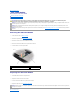
Back to Contents Page Hard Drive Dell™ Studio XPS™ 1640 Service Manual Removing the Hard Drive Replacing the Hard Drive CAUTION: If you remove the hard drive from the computer when the drive is hot, do not touch the metal housing of the hard drive. CAUTION: Before working inside your computer, read the safety information that shipped with your computer. For additional safety best practices information, see the Regulatory Compliance Homepage at www.dell.com/regulatory_compliance.
1 hard drive 3 screws (4) 7. 1 2 hard drive bracket Pull the interposer to disconnect it from the hard drive. hard drive 2 interposer Replacing the Hard Drive 1. Remove the new drive from its packaging. Save the original packaging for storing or shipping the hard drive. NOTICE: Use firm and even pressure to slide the drive into place. If you use excessive force, you may damage the connector. 2. Replace the four screws that secure the hard drive bracket to the hard drive. 3.
Back to Contents Page Keyboard Dell™ Studio XPS™ 1640 Service Manual Removing the Keyboard Replacing the Keyboard CAUTION: Before working inside your computer, read the safety information that shipped with your computer. For additional safety best practices information, see the Regulatory Compliance Homepage at www.dell.com/regulatory_compliance.
3. Replace the thirteen screws that secure the keyboard to the palm rest. NOTICE: The keycaps on the keyboard are fragile, easily dislodged, and time-consuming to replace. Be careful when removing and handling the keyboard. 4. Replace the palm rest (Replacing the Palm Rest).
Back to Contents Page Memory Dell™ Studio XPS™ 1640 Service Manual Removing the Memory Module(s) Replacing the Memory Module(s) CAUTION: Before working inside your computer, read the safety information that shipped with your computer. For additional safety best practices information, see the Regulatory Compliance Homepage at www.dell.com/regulatory_compliance.
1 tab 2 notch NOTICE: If the cover is difficult to close, remove the module and reinstall it. Forcing the cover to close may damage your computer. 3. Replace the base cover (see Replacing the Base Cover). 4. Slide the battery into the battery bay, or connect the AC adapter to your computer and an electrical outlet. 5. Turn on the computer. As the computer boots, it detects the additional memory and automatically updates the system configuration information.
Back to Contents Page Wireless Mini-Card Dell™ Studio XPS™ 1640 Service Manual Removing the Mini-Card Replacing the Mini-Card CAUTION: Before working inside your computer, read the safety information that shipped with your computer. For additional safety best practices information, see the Regulatory Compliance Homepage at www.dell.com/regulatory_compliance.
5. Lift the Mini-Card out of the system board connector. NOTICE: When the Mini-Card is not in the computer, store it in protective antistatic packaging. For more information, see "Protecting Against Electrostatic Discharge" in the safety information that shipped with your computer. Replacing the Mini-Card 1. Remove the new Mini-Card from its packaging. NOTICE: Use firm and even pressure to slide the card into place. If you use excessive force, you may damage the connector. 2.
Back to Contents Page Optical Drive Dell™ Studio XPS™ 1640 Service Manual Removing the Optical Drive Replacing the Optical Drive CAUTION: Before working inside your computer, read the safety information that shipped with your computer. For additional safety best practices information, see the Regulatory Compliance Homepage at www.dell.com/regulatory_compliance.
1 interposer Replacing the Optical Drive 1. Attach the interposer to the optical drive. 2. Place the optical drive in the computer base. 3. Replace the three screws that secure the optical drive to the system board. 4. Turn the computer over and replace the screw that secures the optical drive to the computer base. 5. Replace the palm rest (see Replacing the Palm Rest).
Back to Contents Page Palm Rest Dell™ Studio XPS™ 1640 Service Manual Removing the Palm Rest Replacing the Palm Rest CAUTION: Before working inside your computer, read the safety information that shipped with your computer. For additional safety best practices information, see the Regulatory Compliance Homepage at www.dell.com/regulatory_compliance.
1 touch pad cable 2 display cable 3 palm rest 4 tabs (2) 5 screws (2) Replacing the Palm Rest 1. Align the palm rest tabs and the palm rest with the computer base and gently snap the palm rest into place. 2. Reconnect the keyboard cable and the touch pad cable to the respective system board connectors. 3. Replace the two screws on the top of the palm rest. 4. Turn the computer upside down and replace the fourteen screws in the computer base. 5.
Back to Contents Page Rear Caps Dell™ Studio XPS™ 1640 Service Manual Removing the Rear Caps Replacing the Rear Caps CAUTION: Before working inside your computer, read the safety information that shipped with your computer. For additional safety best practices information, see the Regulatory Compliance Homepage at www.dell.com/regulatory_compliance.
Back to Contents Page Speakers Dell™ Studio XPS™ 1640 Service Manual Removing the Speakers Replacing the Speakers CAUTION: Before working inside your computer, read the safety information that shipped with your computer. For additional safety best practices information, see the Regulatory Compliance Homepage at www.dell.com/regulatory_compliance.
Back to Contents Page
Back to Contents Page Subwoofer Dell™ Studio XPS™ 1640 Service Manual Removing the Subwoofer Replacing the Subwoofer CAUTION: Before working inside your computer, read the safety information that shipped with your computer. For additional safety best practices information, see the Regulatory Compliance Homepage at www.dell.com/regulatory_compliance.
Back to Contents Page System Board Dell™ Studio XPS™ 1640 Service Manual Removing the System Board Replacing the System Board CAUTION: Before working inside your computer, read the safety information that shipped with your computer. For additional safety best practices information, see the Regulatory Compliance Homepage at www.dell.com/regulatory_compliance.
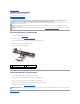
1 system board 2 screws (3) 3 eSATA connector cable connector 4 AC adapter connector cable connector 5 computer base 6 TV tuner card cable connector Replacing the System Board 1. Replace the system board in the computer base. 2. Connect the eSATA connector cable, AC adapter connector cable, and TV tuner card cable to the respective system board connectors. 3. Replace the three screws that secure the system board to the computer base. 4.
19. Turn on the computer. NOTE: After you have replaced the system board, enter the computer Service Tag into the BIOS of the replacement system board. 20. Insert the BIOS upgrade CD that accompanied the replacement system board into the appropriate drive. Follow the instructions that appear on the screen.
Back to Contents Page Dell™ Studio XPS™ 1640 Service Manual NOTE: A NOTE indicates important information that helps you make better use of your computer. NOTICE: A NOTICE indicates either potential damage to hardware or loss of data and tells you how to avoid the problem. CAUTION: A CAUTION indicates a potential for property damage, personal injury, or death. Information in this document is subject to change without notice. © 2008 Dell Inc. All rights reserved.
Back to Contents Page TV Tuner Card (Optional) Dell™ Studio XPS™ 1640 Service Manual Removing the TV Tuner Card Replacing the TV Tuner Card CAUTION: Before working inside your computer, read the safety information that shipped with your computer. For additional safety best practices information, see the Regulatory Compliance Homepage at www.dell.com/regulatory_compliance.