6HUYLFH 0DQXDO 10 Mar 2009
,QIRUPDWLRQ LQ WKLV GRFXPHQW LV VXEMHFW WR FKDQJH ZLWKRXW QRWLFH 'HOO ,QF $OO ULJKWV UHVHUYHG 5HSURGXFWLRQ LQ DQ\ PDQQHU ZKDWVRHYHU ZLWKRXW WKH ZULWWHQ SHUPLVVLRQ RI 'HOO ,QF LV VWULFWO\ IRUELGGHQ 7UDGHPDUNV XVHG LQ WKLV WH[W 'HOO DQG WKH '(// ORJR DUH WUDGHPDUNV RI 'HOO ,QF 2WKHU WUDGHPDUNV DQG WUDGH QDPHV PD\ EH XVHG LQ WKLV GRFXPHQW WR UHIHU WR WKH HQWLWLHV FODLPLQJ WKH PDUNV DQG QDPHV RI WKHLU SURGXFWV 'HOO ,QF GLVFODLPV DQ\ SURSULHWDU\ LQWHUHVW LQ WUDGHPDUNV DQG WUDGH QDPHV RWKHU WKDQ LWV
Table of Contents 1. Precautions 1.1 Safety Warning •••••••••••••••••••••••••••••••••••••••••••••••••••••••1-1 1.2 Caution for safety ••••••••••••••••••••••••••••••••••••••••••••••••••••1-2 1.3 ESD Precautions •••••••••••••••••••••••••••••••••••••••••••••••••••••1-5 2. Product spec and feature 2.1 Product Specifications ••••••••••••••••••••••••••••••••••••••••••••••2-1 2.1.1 Product Overview ••••••••••••••••••••••••••••••••••••••••••••••• •2-1 2.1.
Continued 3.3.11 3.3.12 3.3.13 3.3.14 3.3.15 4. Fuser Control Board ••••••••••••••••••••••••••••••••••••••••• 3-14 LSU ••••••••••••••••••••••••••••••••••••••••••••••••••••••••••••• 3-15 CRUM •••••••••••••••••••••••••••••••••••••••••••••••••••••••••• 3-16 Fuser Drive Ass’y •••••••••••••••••••••••••••••••••••••••••••• 3-16 Pick up roller •••••••••••••••••••••••••••••••••••••••••••••••••• 3-17 Alignment & Troubleshooting 4.1 Alignment and Adjustments ••••••••••••••••••••••••••••••••••••••••4-1 4.1.
Continued 5.7 Top Cover •••••••••••••••••••••••••••••••••••••••••••••••••••••••••••• 5-17 5.8 Reverse Frame ••••••••••••••••••••••••••••••••••••••••••••••••••••• 5-19 5.9 Reverse Drive ••••••••••••••••••••••••••••••••••••••••••••••••••••••• 5-21 5.10 Frame ••••••••••••••••••••••••••••••••••••••••••••••••••••••••••••••• 5-23 5.11 Feed Drive ••••••••••••••••••••••••••••••••••••••••••••••••••••••••• 5-25 5.12 Fuser Unit •••••••••••••••••••••••••••••••••••••••••••••••••••••••••• 5-27 5.
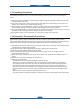
Precautions 1. Precautions In order to prevent accidents and to prevent damage to the equipment please read the precautions listed below carefully before servicing the printer and follow them closely. 1.1 Safety Warning (1) Only to be serviced by appropriately qualified service engineers. High voltages and lasers inside this product are dangerous. This printer should only be serviced by a suitably trained and qualified service engineer.
Precautions 1.2 Caution for safety 1.2.1 Toxic material This product contains toxic materials that could cause illness if ingested. (1) If the LCD control panel is damaged it is possible for the liquid inside to leak. This liquid is toxic. Contact with the skin should be avoided, wash any splashes from eyes or skin immediately and contact your doctor. If the liquid gets into the mouth or is swallowed see a doctor immediately. (2) Please keep Drum cartridge and Toner Cartridge away from children.
Precautions 1.2.3 Handling Precautions The following instructions are for your own personal safety, to avoid injury and so as not to damage the printer (1) Ensure the printer is installed on a level surface, capable of supporting its weight. Failure to do so could cause the printer to tip or fall. (2) The printer contains many rollers, gears and fans. Take great care to ensure that you do not catch your fingers, hair or clothing in any of these rotating devices.
Precautions 1.2.5 Disregarding this warning may cause bodily injury (1) Be careful with the high temperature part. The fuser unit works at a high temperature. Use caution when working on the printer. Wait for the fuser to cool down before disassembly. (2) Do not put finger or hair into the rotating parts. When operating a printer, do not put hand or hair into the rotating parts (Paper feeding entrance, motor, fan, etc.). If do, you can get harm.
Precautions 1.3 ESD Precautions Certain semiconductor devices can be easily damaged by static electricity. Such components are commonly called “Electrostatically Sensitive (ES) Devices” or ESDs. Examples of typical ESDs are: integrated circuits, some field effect transistors, and semiconductor “chip” components. The techniques outlined below should be followed to help reduce the incidence of component damage caused by static electricity.
Product spec and feature 2. Product spec and feature 2.1 Product Specifications 2.1.1 Product Overview Concept Target A4 Tandem CMFP to Maximize office Productivity SMB (Office Work for Heavy Color Print/Copy/Scan) - Scan, Copy, Print, Fax 4 in 1 MFP - Speed : 20/20 PPM (A4) - Resolution : 2400x600 dpi (effective output) - CPU : 360 Mhz - Memory : 128 MB - Toner Cartridge Life (Color/Black) : 5K / 5.
Product spec and feature 2.1.2 Specifications Product Specifications are subject to change without notice. See below for product specifications. 2.1.2.
Product spec and feature Item Dell 2145cn Windows 2000/XP/2003/Vista/2008(include 64bit) Supporting OS Various Linux OS including Red Hat 8.0~9.0, Mandrake 9.2~10.1, SuSE 8.2~9.2 and Fedora Core 1~4 Mac OS X 10.3~10.4 and Universial Mac Default Driver PCL6 Driver feature Watermark Overlay N-up printing Poster printing Duplex Quality (Best/Normal/Draft) Color mode (Color, Gray scale) Copies Setting (Window Only) Color spec.
Product spec and feature 2.1.2.3 Interface Item Dell 2145cn Parallel N/A USB USB 2.0, USB host 2.0(Scan to USB, USB print) Hard Disk OPTION Network Ethernet 10/100 Base TX Wireless OPTION LCD & Button 16 x 2 line LCD (Yellow BackLight) Foreign Device Interface Yes (EDI) 2.1.2.4 Scan Item Scan method Scan Speed Resolution Color CCD Linearity, Halftone about 15 sec at 300dpi,USB2.0,P4 3.0GHz, 512M /Ltr Gray about 20 sec at 300dpi,USB2.0,P4 3.
Product spec and feature 2.1.2.5 Copy Item Copy Speed FCOT (B&W) FCOT (Color) Dell 2145cn Simplex Copy Speed(A4) 20cpm (A4) Duplex Copy Speed(A4) 6200ND/6210FX : 6.
Product spec and feature Item Special Copy Dell 2145cn ID Card Copy Yes(Platen Only) Auto fit Yes(Platen Only) Margin Shift Yes Book Copy Yes Auto Suppression Yes Covers No Transparencies No Create Booklet No N-up copy 2-up, 4-up Clone Yes (Platen Only) Poster Yes (Platen Only) 2.1.2.6 Fax Item Dell 2145cn Compatibility ITU-T G3 Communication System PSTN/PABX Modem Speed 33.6Kbps TX Speed 3sec(Mono/Standard/ECM-MMR.ITU-T G3 No1.
Product spec and feature Item Telephone Features Functions Report & List Print out Sound Control Dell 2145cn Caller ID No External Phone Interface Yes Mail Box No Voice Request No TTI Yes RTI Yes Polling No Earth/Recall No Auto Reduction Yes SMS No RDS Yes Tx/Rx Journal Yes Confirmation 2 types available (with Image TCR, w/o image TCR, Mono Only) Auto Dial List Yes System Data List List all user setting Ring Volume Yes (Off, Low, MED, HIGH) Key Volume Yes (On, Off) Spe
Product spec and feature 2.1.2.7 Paper Handling Item Dell 2145cn Standard Capa. 250-sheet Cassette Tray, 100 MP Max. Capa. 850 sheets @ 75g/້ Printing Max. Size 216 X 356((8.5” x 14”) Min.
Product spec and feature 2.1.2.8 CRU Item 5 (C/M/Y/K toner, PTB) K toner cartridge: CLP-K660B C toner cartridge: CLP-C660B M toner cartridge: CLP-M660B Y toner cartridge: CLP-Y660B Paper Transfer Belt: CLP-T660A No.
Product spec and feature 2.1.2.9 FRU Item Sec_Code Expected Life (Pages) JC91-00934A(110V) Fuser 100 K JC91-00933A(220V) Pick-up Roller (Main, MP) JC90-00932A(Main) 70K JC96-02686B (MP) JC97-03077A (CST) Friction Pad 70K JC97-02892A(MP) [DADF/ADF] Pick-up Roller JC97-03070A(DADF) 80K [DADF/ADF] Friction Pad JC97-03069A(DADF) 20K 2.1.2.
Product spec and feature ■ Machine Life Life (Expected Average based on AMPV usage ratio) CRU/FRU Modes Expected Life pages Images Total Page 200,000 200,000 Color only (page) Mono only (page) Mono (40%) 80,000 80,000 Color (60%) 120,000 120,000 Cyan 5,000 5,000 5,000 5,000 Magenta 5,000 5,000 5,000 5,000 SET Toner Cartridge (5% coverage) Total Image Max.
Product spec and feature 2.1.2.11 Environment Item Acoustic Noise Level(Sound Power/Pressure) Dell 2145cn Print & Copy Less than 53 dBA print @ CST Less than 54 dBA copy @ CST Less than 56 dBA print & copy @ SCF &MP Standby Less than 35 dBA Sleep Background noise level 110-127 VAC, 50/60Hz Input Voltages 220-240 VAC,50/60Hz Power Switch Power Consumption Dimension (W x D x H) Ready Less than 82W AVG.
Product spec and feature 2.1.2.12 Option ACCESSORIES PART NUMBER Memory module • CLP-MEM201 : 128MB • CLP-MEM202 : 256MB Optional tray 2 CLX-S6240A ( 500 Sheet ) IEEE 802.
Product spec and feature 2.1.
Product spec and feature 2.
Product spec and feature ■ Engine Layout 13 10 2 7 12 6 5 4 1 11 3 9 8 1 OPC 8 Pick-up Roller 2 Charge Roller 9 Regi Roller 3 MP Roller 10 Exit Roller 4 Deve Roller 11 Duplex Roller 5 Transfer Roller 12 Reverse middle Roller 6 Heat Roller 13 Reverse Exit Roller 7 Pressure Roller 2-16
Product spec and feature ■ DADF Dadf Pickup Roll. Regi. Roll. Scan Area (CCD) Middle Roll. Exit Roll.
Product spec and feature 2.2.1 Main parts of system 1) PTB Unit (Paper Transfer Belt) PTB stands for Image Transfer Belt. An image developed on the Toner Cartridge is transferred first to the PTB. This is called the T1 Transfer Paper Charge Roller. Images are built up in layers on the PTB. First the Yellow (Y) color image is created on the Toner Cartridge and transferred to the PTB. Next the Magenta (M) color image is created on the Toner Cartridge and transferred to the PTB.
Product spec and feature 2) Transfer Roller Once the complete, full color, image, has been built up on the PTB the Transfer Roller is used to transfer the image on to paper. 3) FCT (First Cassette Tray) It stores and automatically feeds print paper. Pick-up Roller picks up paper, controls drive, feeds paper, removes static electricity, and so on. > Spec.
Product spec and feature 5) MPT (Multi Purpose Tray) The Multi-Purpose Tray not only feeds general printing paper but is also used for many other kinds of paper such as those paper sizes not supported by the cassette, envelopes, etc. > Spec.
Product spec and feature 7) Fuser Unit This unit consists of IH-HEAT ROLLER, Thermostats and a Thermistor. It melts and fuses the toner, transferred by the transfer roller onto the paper, by applying pressure and high temperature to complete printing job. * Heat Lamp : New Part - Dual Lamp Type * Fusing system : Belt fusing type - Heat roller : Pipe type (Lamp inside) - Pressure roller - Fuser roller - Belt * Thermistor - Temperature-Measuring Device * Thermostat - Critical Temperature-Detecting Device 1.
Product spec and feature 8) LSU LSU consists of LD(Laser Diode) and polygon motor control. When the controller generate the printing signal LD will turn on and Polygon motor starts. If the receiving part in LSU detect the beam and then Hsync is generated. When the rotation of polygon motor is steady, it is time of LSU ready status for printing. If either of two condition is not satisfied, LSU error is expected.
Product spec and feature 12) HVPS (High Voltage Power Supply) The HVPS creates the high voltages (Transfer, Charge, Attr, Supply DC, Supply AC) used for the electro photographic process. The high voltage is created from the 24V line from the SMPS. High Voltage output is supplied to the toner cartridge, PTB unit. 13) Main Controller PBA The Main controller PBA is very important as it is the heart of printer. It has several major function blocks.
Product spec and feature 17) Scan Part 1) Pictorial signal input part : output signal of CCD passes through MP Cap change to AFE, and defined signal between AFE and Image Processor processes the Image signal. When AFE accept each pixel, CDS(Correlated Double Sampling ) technique which samples arm-level twice is used on each pixel by using IP signal.
Product spec and feature ଝGIP Block Diagram 1) Scanning Device: Color CCD (Charge Coupled Device) Module 2) Supported Operating Systems: Windows 98/2000/NT4.0/ME/XP, MAC (English only) 3) Compatibility: TWAIN Standard 4) Maximum Scan Width: 216mm (8.5 inches) 5) Effective Scan Width: 208mm (8.2 inches) 6) Optical Resolution: 600x1200 dpi 7) Interpolated Resolution: Maximum 4800 dpi 8) Preview Scan: 75 dpi 9) Scan Modes/Speeds: (USB 2.0, 300dpi, Letter Size, Pentium4 2.
Product spec and feature 18) FAX section ଝGBlock Diagram BLOCK DIAGRAM Isolation Barrier Main Board Interface 20pin Connector 5V VOL_0~VOL_2 KEYCLICK SPK_CTL MC34119 5V CML SPK_OUT External Circuitry SPKER 5V CML AOUT Si3018 Si2435 3.3V GND RXD TXD nCTS nRTS RX RAM/ROM Hybrid and dc Termination Serial Interface nDCD ESC nRI Microcontroller DSP DAA Interface nINT nRESET XTALO 4.
Product spec and feature ଝGSignal Transition of DAA Solution Line Interface Signal of Tel Line and LSD is Analog Signal. There are a A/D and a D/A Converter in the LSD, so Analog Signal from Tel Line is converted in Digital through a A/D Converter in the DAA and transferred to the SSD by the DIB Transformer. Digital Signal from the SSD is converted to Analog by a D/A Converter in the DAA and transferred to Tel Line.
Product spec and feature 3) Speaker Driver The AOUT signal from the Si2435 modem chip is only available in the serial DTE interface mode. AOUT is a 50% duty cycle, 32kHz, square wave pulse-width modulated (PWM) by voice band audio, such as cal progress tones. Application Network PSTN (RJ-11) Communication Mode Half-Duplex, ITU V.8, V.34, V.17, V.29, V.21, V.27ter, ECMModem will auto train down only. Communication Standard ITU-T Group 3 Max. Modem Speed 33.
Product spec and feature 2.2.
2-30 REVERSE I/F FAN_SMPS (CHORUS3) S3C26L0 SMPS LSU_Y/M LSU_C/K HVPS SCAN I/F LSU MOT FUSER CCD I/F (LPEC3) STEP MOT THERMISTOR COVER OPEN FAX S4LD171 PTB BLDC_DEV BLDC_OPC ENVIRONMENT SENSOR USB HOST DEVE_CRUM USB N/W SCF ISP1761 Product spec and feature 2.2.2.
Product spec and feature • Memory : - RAM : DDR2 Default 128MB + Option 128/256MB - ROM : 16MB+8MB - EEPROM : 64kb • Peripherals : - USB 2.
Product spec and feature 2.2.2.2 Power Flow • SMPS - Type V (standard type) - +24V : For use Mechanical Part (Motor & Actuator (Solenoid, Clutch)), CCDM - +5V : Logic, Analog, Sensor • Main B’D - Supply From SMPS +5V - Power Supply with Regulator (3.3V & 1.2V & 1.0V : Switching Regulator) - 3.3V : I/O Operating (Digital & Analog) - 1.
Product spec and feature 2.2.2.
Product spec and feature Input Duty (EDC mode display) Output Voltage/Current Load Read voltage (ADC) Tolerance CHARGER Y,M,C,K 169(66%) -1170V 200M - 3% SUP DC Y,M,C,K 100(39%) -295V 68pF - 3% DEVE AC Y,M,C,K AC freq2.6kHz AC PWM 92(36%) AC Vpp PWM 65(25%) 174.0V (about 1740V) [ AC JIG ] 68pF - 1.5% Transfer_Y,M,C,K 97(38%) 14uA 90M 1.7V (132) 3% ATTR 108(42%) 950V 100M 0.
Product spec and feature 2.2.2.4 Fuser Drive Board 2 PHOTO TRIAC 3 TRIAC 1 4 VARISTOR FUSE Dell 2145cn • Zero crossing photo triac • 1 lamp (800W) Pulse control 1 2 3 4 INLET AC FUSER CONTROL (from Main board) FUSER AC (to Fuser lamp) SMPS AC (to SMPS) 1 2 3 AC from FDB NC (not used) 24V,5V to main board 2.2.2.
Product spec and feature ■ Input/Output connector DC Output connector (CN3) PIN No. Pin Assign Description PIN No.
Disassembly and Reassembly 3. Disassembly and Reassembly 3.1 General Precautions on Disassembly When you disassemble and reassemble components, you must use extreme caution. The close proximity of cables to moving parts makes proper routing a must. If components are removed, any cables disturbed by the procedure must be restored as close as possible to their original positions. Before removing any component from the machine, note the cable routing that will be affected.
Disassembly and Reassembly 3.2 Screws used in the printer The screws listed in the table below are used in this printer. Please ensure that, when you disassemble the printer, you keep a note of which screw is used for which part and that, when reassembling the printer, the correct screws are used in the appropriate places.
Disassembly and Reassembly Sec_Code Location 6003-000196 Description Qty SCREW-TAPTITE;PWH,+,B,M3,L10,NI PLT,SWRCH18A 10 SCREW-TAPTITE;PWH,+,-,B,M3,L6,ZPC(WHT),SWRCH18A,- 1 ELA HOU-UNIT_CASSETTE 6003-000264 6003-000196 MEA-COVER_CASSETTE SCREW-TAPTITE;PWH,+,B,M3,L10,NI PLT,SWRCH18A 2 6003-000261 MEA-KNOCK_UP_PLATE SCREW-TAPTITE;BH,+,-,B,M3,L6,ZPC(WHT),SWRCH18A,- 1 6003-000196 MEA-GUIDE PAPER DUP SCREW-TAPTITE;PWH,+,B,M3,L10,NI PLT,SWRCH18A 2 6003-000282 ELA UNIT-LSU SCREW-TAPTITE;BH,
Disassembly and Reassembly Sec_Code Location Description Qty 6003-000269 MAIN-BD SCREW-TAPTITE;BH,+,-,S,M3,L6,ZPC(WHT),SWRCH18A,- 4 6003-000269 MEA-COVER REVERSE SCREW-TAPTITE;BH,+,-,S,M3,L6,ZPC(WHT),SWRCH18A,- 1 6003-000269 SMPS SCREW-TAPTITE;BH,+,-,S,M3,L6,ZPC(WHT),SWRCH18A,- 4 SCREW-TAPTITE;BH,+,-,S,M3,L6,ZPC(WHT),SWRCH18A,- 8 SCREW-TAPTITE;BH,+,-,S,M4,L6,ZPC(WHT),SWRCH18A,- 1 6003-000269 ELA UNIT-BRACKET_MAIN 6003-000301 6003-000196 MOTOR BRKT SCREW-TAPTITE;PWH,+,B,M3,L10,NI PLT,S
Disassembly and Reassembly 3.3 Disassembly Procedure The description of disassembly and reassembly in this manual is listed according to the disassembly procedures. 3.3.1 COVER Rev Exit & COVER L/R 1. Remove the three screws.Remove the Cover Rev Exit Ass’y. 3. Remove the two screws. 4. Remove the two screws.Unlatch the two hooks before remove the COVER L/R 2. Remove the two screws.
Disassembly and Reassembly 5.Push the hook with any tool, Release the Cover L/R from the SET in the direction of arrow. (Cover L: unplug fan harness) 6. Done. 3.3.2 Cover Front Ass’y 1. Release the L/R link.
Disassembly and Reassembly 2. Remove the 6 screws from both side. And remove the right/left Hinge Cover. 3. Use a thin, less than 2 mm flat-blade screw driver in the upper left hand corner of the hinge, push the screwdriver towards the printer to push the hinge out of the printer.
Disassembly and Reassembly 3.3.3 COVER REAR & COVER MIDDLE REAR 1. Remove the six screws.Pull the Cover Rear. 3. Unplug the connector.(3 pin) 2. Remove the 2 screws. Pull the Cover Middle Rear. 4. Done.
Disassembly and Reassembly 3.3.4 SCAN Ass’y 1. Unplug the two harness from the Main BD, Remove the one screw and Release the one Ground harness. 3. Pull the Scanner from the SET in the direction of arrow 2. Push down on the black wedge using a Flathead screwdriver, and push the scan assembly arm back.
Disassembly and Reassembly 3.3.5 DADF 1. Disassemble the cover-connector in the indicated direction. 2. Pull the DADF from the SET in the direction of arrow.
Disassembly and Reassembly 3.3.6 Reverse Ass’y 1. Unplug the three harness from the Reverse Joint BD, Remove the one screw and Release the one Ground harness. 3. Remove the 4 screws. Pull the Reverse Ass’y from the SET in direction of arrow. 4. Done. 2. Remove the 4 screws. Pull the Cover Middle Open.Pull the Reverse Ass’y from the SET in direction of arrow.
Disassembly and Reassembly 3.3.7 COVER MIDDLE Ass’y 1. Unplug the three harness from the Main BD. 3. Done. 2. Remove the six screws.Pull the Cover Middle Ass’y from the SET in direction of arrow.
Disassembly and Reassembly 3.3.8 HVPS 1. Remove 8 screw and unlatch 4 hook after remove left side cover 2. Take out the HVPS. And unplug the two cables at the bottom and 5 cables (including 2 flat cable) NOTE - Be careful of taking out the HVPS because there are 16 High Voltage Terminal behind HVPS. 3.3.9 Main Board 1. Unplug the connectors and all the harness 2. Pull the MAIN BD after remove the 4 screws.
Disassembly and Reassembly 3.3.10 SMPS Board 1. Unplug the Harness, as shown below. 2. Remove the 4 screws, and release the SMPS Board from the SET. 3.3.11 Fuser Control Board 1.Unplug the Harness. 2. Remove the 4 screws, and release the Fuser control board from the SET.
Disassembly and Reassembly 3.3.12 LSU 1. Remove the main board after unplug connectors and all harness 3. Remove the 3 screws. And remove the Main Bracket Assembly. 2. To remove the Main Bracket assembly , remove 4 screws and SMPS board. 4. Pull the LSU after remove 4 screw.
Disassembly and Reassembly 3.3.13 CRUM 1. Remove the CRUM after unlatch the lever. 3.3.14 Fuser Drive Ass’y 1. Remove the Duct fuser after remove the 2 screw. 2. Pull the Fuser Drive assembly after remove 5 screw and unplug connector.
Disassembly and Reassembly 3.3.15 Pick up roller 1. Remove the Pick up roller.
Alignment and Troubleshooting 4. Alignment and Troubleshooting This chapter describes some of the main service procedures including: Using the Tech mode; Clearing paper jam and test patterns. • Tips for avoiding paper jams, Clearing paper jams. • Solving other problems. 4.1 Alignment and Adjustments 4.1.1 Control Panel overview 1 Speed buttons Allows you to store frequently-dialed fax numbers and enter them with the touch of a few buttons.
Alignment and Troubleshooting 19 Reduce/Enlarge Makes a copy smaller or larger than the original. 20 Duplex Allows you to print documents on both sides of the paper. 21 USB Print Allows you to directly print files stored on a USB Memory device when it is inserted into the USB memory port on the front of your machine. 22 Number keypad Dials a number or enters alphanumeric characters. 23 On Hook Dial Engages the telephone line. 24 Stop/Clear Stops an operation at any time.
Alignment and Troubleshooting 4.1.3 Jam Removal ■ Clearing paper jams When a paper jam occurs, the warning message appears on the display screen. Refer to the table below to locate and clear the paper jam.
Alignment and Troubleshooting ■ Paper Path Simplex Pass Finisher Pass Duplex Pass MP Feed Cassette Feed SCF Feed 4-4
Alignment and Troubleshooting 4.1.3.1 In the paper feed area If paper is jammed in the paper feed area, follow the next steps to release the jammed paper. 1. Using the handle, completely open the front cover. 3. Close the front cover. 4. Pull the tray open. 2. Carefully remove the paper by pulling in the direction as shown below. 5. Remove the jammed paper by gently pulling it straight out as shown below.
Alignment and Troubleshooting 6. To replace the tray, lower the rear edge, align it with the slot, and slide it into the machine. 7. Open the front cover and close it. The machine will resume printing. 4.1.3.2 In the multi-purpose tray When you print using the Multi-purpose Tray and the machine detects that there is either no paper or the paper has been improperly loaded, follow the next steps to release the jammed paper. 1.
Alignment and Troubleshooting 5. Pull the paper out gently. 8. Remove the jammed paper by pulling in the direction shown. To avoid tearing the paper, pull it out gently and slowly. 6. Replace the tray. If you cannot find the jammed paper, or if there is any resistance removing the paper, stop pulling and go to step 8. 7. Using the handle, completely open the front cover. 9. Close the front cover firmly. The machine will resume printing.
Alignment and Troubleshooting 4.1.3.3 In the fuser unit area If paper is jammed in the fuser unit area, follow the next steps to release the jammed paper. 1. Open the top cover. 3. Open the inner cover using the handle on it and carefully take the jammed paper out of the machine. 2. Open the inner cover using the handle. 4. Pull up the paper jam lever to loose the fusing part of the fuser unit and carefully take the jammed paper out of the machine.
Alignment and Troubleshooting 5. Press down the paper jam lever to fasten the fusing part. 7. Lowering down the scan unit gently and slowly until it is completely closed. Make sure that it is securely latched. Be careful not to pinch your fingers! 6. Close the inner cover.
Alignment and Troubleshooting 4.1.3.4 In the paper exit area If paper is jammed in the paper exit area, follow the next steps to release the jammed paper. 1. If a long portion of the paper is visible, pull it straight out. Open and close the front cover firmly. The machine will resume printing. 3. Open the cover of reverse unit using the handle on it and carefully take the jammed paper out of the machine.
Alignment and Troubleshooting 5. Lowering down the scan unit gently and slowly until it is completely closed. Make sure that it is securely latched. Be careful not to pinch your fingers! 6. After removing the jammed paper, check for paper which may be jammed in other parts of the machine. 7. Close the rear cover. If you cannot find the jammed paper, or if there is any resistance removing the paper, stop pulling and go to step 6.
Alignment and Troubleshooting 4.1.3.5 In the optional tray If paper is jammed in the optional Tray, follow the next steps to release the jammed paper. 1. Pull the optional Tray open. After you pull it all the way out, lift up the front part of the tray slightly to release the tray from the machine. 3. Slide the tray back into the machine and close the two jam covers. 4. Open the front cover. 2.
Alignment and Troubleshooting 4.1.4 System setup 4.1.4.1 Accessing to menus The next steps are the example to print the menu map of this machine, and they are the general way to select menu and configure your machine. 1. Make sure your machine is properly connected all the necessary cables, and turn on the machine. 2. Press the Menu button until you see the menu (ex. Information) you want on the bottom line of the display. 3. Press the Enter button to access the menu. 4.
Darkness Multi Send Delay Send Priority Send Forward Secure Receive Add Page Cancel Job Fax Feature Sending Redial Times Redial Term Prefix Dial ECM Mode Send Report Image TCR Dial Mode Receiving Receive Mode Ring to Answer Fax Setup TCP/IP Ethernet Speed Wireless Clear Setting Network Info Network Stamp RCV Name RCV Start Code Auto Reduction Discard Size Junk Fax Setup DRPD Mode Duplex Print Change Default Resolution Darkness Auto Report Fax Setup (Continued) Clear Setting All Settings Fax Setup Cop
Alignment and Troubleshooting 4.1.4.3 Maintenance This chapter provides information for maintaining your machine and the toner cartridge.
Alignment and Troubleshooting REPORT/LIST DESCRIPTION Completed Job The Completed Job page shows the list of completed print jobs. The list contains up to 50 files from the latest print jobs. Net Auth Log This list shows users and their IDs who logged in the domain. Printing a report 1. Press Menu until System Setup appears on the bottom line of the display and press OK. 2. Press the left/right arrow until Report appears and press OK. 3.
Alignment and Troubleshooting 1 2 3 4 4-17
Alignment and Troubleshooting 1. Date& Time, Fax number, Fax Name, Model Name - shows actual printed date of configuration pages, Fax number, Fax/Model name. 2. Options - shows various options set up in the printer. 3. Firmware/ Emulation version - shows date and version of firmware/emulation (PCL5Ce,PS3,PCL6,SPL-C) 4. IP Address/Memory Size - shows the IP address and memory installed in the printer.
Alignment and Troubleshooting 1 2 3 4 Supplies Information Report shows the life of consumables. 1. Total Page Count/Page count (Pages) 2. The Life of Fuser/Toner/PTB/Various Rollers - Fuser (Page), Toner, PTB(%), Rollers (Page) 3. Product Date/Last used Date 4. First Installed Date 5.
Alignment and Troubleshooting ■ ADJUSTING THE COLOR CONTRAST Color menu allows you to adjust the color setting. 1. Press Menu until System Setup appears on the bottom line of the display and press OK. 2. Press OK when Maintenance appears. 3. Press the left/right arrow until Color appears and press OK. 4. Press the left/right arrow until the menu you want appears on display and press OK. • Custom C olor:Allows you to adjust contrast color by color. Default optimizes color automatically.
Alignment and Troubleshooting ■ CLEANING YOUR MACHINE To maintain print and scan quality, follow the cleaning procedures below each time the toner cartridge is replaced or if print and scan quality problems occur. Cleaning the outside Clean the cabinet of the machine with a soft lint-free cloth. You can dampen the cloth slightly with water, but be careful not to let any water drip onto or into the machine.
Alignment and Troubleshooting 6. Locate the long strip of glass (LSU) inside the cartridge compartment, and gently swab the glass to see if dirt turns the white cotten black. 7. Reinstall all the compartments into the machine, and close the front cover. 8. Plug in the power cord and turn the machine on. Cleaning the scan unit Keeping the scan unit clean helps ensure the best possible copies. We suggest that you clean the scan unit at the start of each day and during the day, as needed. 1.
Alignment and Troubleshooting ■ MAINTAINING THE CARTRIDGE Toner cartridge storage To get the most from the toner cartridge, keep the following guidelines in mind: • Do not remove the toner cartridge from its package until ready for use. • Do not refill the toner cartridge. The machine warranty does not cover damage caused by using a refilled cartridge. • Store toner cartridges in the same environment as your machine.
Alignment and Troubleshooting 3. Holding both handles on the toner cartridge, thoroughly rock it from side to side to evenly distribute the toner. 5. Close the front cover. Make sure the cover is securely latched. 4. Slide the toner cartridge back into the machine.
Alignment and Troubleshooting ■ REPLACING THE TONER CARTRIDGE The machine uses four colors and has a different toner cartridge for each one: yellow (Y), magenta (M), cyan (C), and black (K). • The status LED and the toner-related message on the display indicates which each individual toner cartridge should be replaced. • For the Dell 2145cn, incoming faxes are saved in memory. At this stage, the toner cartridge needs to be replaced. Check the type of toner cartridge for your machine. 1.
Alignment and Troubleshooting 7. Make sure that the color of the toner cartridge matches the color slot and then grasp the handles on the toner cartridge. Insert the cartridge until it clicks into place. 8. Close the front cover. Make sure that the cover is securely latched, and then turn the machine on.
Alignment and Troubleshooting Clearing the Toner Empty message When the Toner Empty message appears you can configure not to see this message again not to disturb you. 1. Press Menu until System Setup appears on the bottom line of the display and press OK. 2. Press the Scroll buttons until Maintenance appears and press OK. 3. Press the Scroll buttons until CLR Empty Msg. appears and press OK. 4. Press the left/right arrow until the color menu you want appears on display and press OK. 5.
Alignment and Troubleshooting 5. Holding the handle on the new paper transfer belt, align it with the slots on the inside of the front cover. 6. Lower the paper transfer belt until it is parallel with the front cover and firmly seated. 7. Close the front cover firmly. 8. Turn the machine on.
Alignment and Troubleshooting Checking replaceables If you experience frequent paper jams or printing problems, check the number of pages the machine has printed or scanned. Replace the corresponding parts, if necessary. 1. Press Menu until System Setup appears on the bottom line of the display and press OK. 2. Press the left/right arrow until Maintenance appears and press OK. 3. Press the left/right arrow until Supplies Life appears and press OK. 4.
Alignment and Troubleshooting ■ MANAGING YOUR MACHINE FROM THE WEBSITE If you have connected your machine to a network and set up TCP/IP network parameters correctly, you can manage the machine via Dell’s Web Service, an embedded web server. Use Web Service to: • View the machine’s device information and check its current status. • Change TCP/IP parameters and set up other network parameters. • Change the printer properties. • Set the machine to send email notifications to let you know the machine’s status.
Alignment and Troubleshooting 4.1.4.4 Periodic Defective Image If an image defects appears at regular intervals on the printed-paper, it is due to a faulty or damaged roller. Refer to the table below and check the condition of the appropriate roller. No Roller Period Phenomenon 1 OPC Drum 75.4mm White and Black Spots 2 Charge Roller 26.7mm White/Black Spot and Periodic Band 3 Supply Roller 40.8~41mm Periodic Band (by little difference of density) 4 Developing Roller 30.
Alignment and Troubleshooting 13 10 2 7 12 6 5 4 1 11 3 9 8 1 OPC 8 Pick-up Roller 2 Charge Roller 9 Regi Roller 3 MP Roller 10 Exit Roller 4 Deve Roller 11 Duplex Roller 5 Transfer Roller 12 Reverse middle Roller 6 Heat Roller 13 Reverse Exit Roller 7 Pressure Roller 4-32
Alignment and Troubleshooting 4.1.4.5 F/W Upgrade • USB and Network port are used to F/W upgrade. • Network applications (EWS) can be used for network port upgrade. • Notice : In special mode upgrade, kernel waste header information for Dell 2145cn.
Alignment and Troubleshooting 2) Using SWS • F/W upgrade using EWS - Home -> Maintenance -> Firmware Upgrade 4-34
Alignment and Troubleshooting 4.1.4.6 EDC Mode ■ Method to enter 1. Power - On the printer, and wait until the “READY” message appearing on LCD Panel. 2. Push button like next time “Menu -> Stop -> Left arrow -> Back -> OK -> Right arrow” 3. “COMPONEMT TEST Press Menu Key” ■ Keys Key Description Menu Move to the top menu Left Arrow Move test item OK Start testing or select Sub-item Right arrow Move test item Back Move upper menu Stop Stop testing ■ EDC Menu 0.
Alignment and Troubleshooting 1. Sensor Status Key Description Regi. Sensor If actuator is checked by sensor, "Without Paper" message will be displayed. if not, "With Paper" will be. Exit Sensor If actuator is checked by sensor, "Without Paper" message will be displayed. if not, "With Paper" will be. MP Empty If paper exists in the MP tray, "With Paper" will be displayed. If not, "Without Paper" will be. T1 Paper Empty If paper exists in the 1st tray, "With Paper" will be displayed.
Alignment and Troubleshooting 4. Clutch/Sol. Key Description T1 P - up Clutch When “OK” key is pushed after ”ON” message displayed, clutch turn on. pick up clutch will be turn off after 5 seconds and ”OFF” message will be displayed. T2 P - up Clutch When “OK” key is pushed after ”ON” message displayed, clutch turn on. pick up clutch will be turn off after 5 seconds and ”OFF” message will be displayed.
Alignment and Troubleshooting 7. DEV Control Key Description Charger If “OK” key is pushed after “ON” displayed, Charger voltage will be turned on. Dev DC Y If “OK” key is pushed after “ON” displayed, Dev DC Y will be turned on. Dev DC M If “OK” key is pushed after “ON” displayed, Dev DC M will be turned on. Dev DC C If “OK” key is pushed after “ON” displayed, Dev DC C will be turned on. Dev DC K If “OK” key is pushed after “ON” displayed, Dev DC K will be turned on.
Alignment and Troubleshooting 4.1.4.7 Tech Mode ■ How to Enter Tech Mode In service (tech) mode, the technician can check the machine and perform various test to isolate the cause of a malfunction. While in Tech mode, the machine still performs all normal operations. To enter the Tech mode, press “Menu → # → 1 → 9 → 3 → 4 → Menu” in sequence, and the LCD briefly displays ‘TECH Menu’, the machine has entered service (tech) mode.
Alignment and Troubleshooting Depth 1 Depth 2 Depth 3 Depth 4 Machine Test Fuser Offset StandBy Temp. Run Temp. 101-185mm Temp. 186-216mm Temp. 90 gms Temp. Bond Temp. OHP Temp. Cardstock Temp. Env. Temp. Label Temp.
Alignment and Troubleshooting CLEAR ALL MEMORY The function resets the system to factory default settings. This function is used to reset the system to the initial value when the product is functioning abnormally. All the values are returned to the default values, and all the information, which was set by the user, will be erased. < Method > 1. Select the [Data Setup - Clear All Mem.] at the TECH MODE. 2. Push the ENTER button. 3. Select you country. 4. Push the ENTER button then it will clear all memory.
Alignment and Troubleshooting ■ Machine Test SWITCH TEST Use this feature to test all keys on the operation control panel. The result is displayed on the LCD window each time you press a key. MODEM TEST Use this feature to hear various transmission signals to the telephone line from the modem and to check the modem. If no transmission signal sound is heard, it means the modem part of the main board malfunctioned. DRAM TEST Use this feature to test the machine’s DRAM.
Alignment and Troubleshooting 4.1.5 Error Message Messages appear on the control panel display to indicate the machine’s status or errors. Refer to the tables below to understand the messages’ meaning and correct the problem if necessary. Messages and their meanings are listed in alphabetical order. • xxx indicates the media type. • yyy indicates the tray. Message Meaning Suggested Solution [COMM. Error] The machine has a communication problem. Ask the sender to try again.
Alignment and Troubleshooting Message Meaning Suggested Solution Data Write Fail Check USB Mem. Storing to the USB memory failed. Check the available USB memory space. Document Jam The loaded original has jammed in the DADF. Clear the jam. Door Open/Check Transfer Belt The front cover is not securely latched. Close the cover until it locks into place. Duplex Jam 0 Check Inside Paper has jammed during duplex printing. This is applicable only to machines with this feature. Clear the jam.
Alignment and Troubleshooting Message Meaning Suggested Solution Global Server Comm Error This error message displays when there is a communication error between the global server and the device. Try again. Contact a LDAP Server administrator. Group Not Available You have tried to select a group location number where only a single location number can be used, such as when adding locations for a Multiple Send operation. Use a speed dial number or dial a number manually using the number keypad.
Alignment and Troubleshooting Message Meaning Suggested Solution Not Available Try Again Later Can not perform the task immediately because too many tasks are running at once. Try again when current task is completed. Non DELL Toner The color toner cartridge which the arrow indicates is not a Dell-genuine cartridge. Press OK to toggle the message to Stop or Continue. Stop You can select either Stop or Continue with the left/right arrow.
Alignment and Troubleshooting Message Meaning Suggested Solution Reverse Jam 0 Check Inside Paper has jammed in the paper fuser area and In the cover of reverse unit area. Clear the jam. Reverse Jam 1 Check Inside Paper has jammed In the cover of reverse unit area or in the rear cover. Clear the jam. Scanner locked The scanner module is locked Unlock the scanner and press Stop/Clear. Self Diagnostics Temperature The engine in your machine is checking problems detected. Wait a few minutes.
Alignment and Troubleshooting 4.2 Troubleshooting 4.2.1 Procedure of Checking the Symptoms Before attempting to repair the printer first obtain a detailed description of the problem from the customer. Power On OP Panel ON? - No Power - Power Module error - Main PBA error - LCD Panel error Ready or Power save Indicate Error Message Test Print Printing Quality is Normal? Refer to "Solution of Image Problem" END 4-48 Refer to Error Message
Alignment and Troubleshooting 4.2.2 Image quality problems 1) Vertical Black Line and Band Description 1. Straight thin black vertical lines are shown in the print-out. 2. Dark black vertical bands are shown in the print-out. Digital Printer Digital Printer Digital Printer Digital Printer Digital Printer Replace the toner Cartridge and test again. Replace the toner Cartridge and test again. 3. Damaged paper transfer Belt(PTB) or Contaminated on PTB. Replace the PTB unit and test again. 4.
Alignment and Troubleshooting 2) Vertical White Line Description White vertical voids in the image. Digital Printer Digital Printer Digital Printer Digital Printer Digital Printer Replace the toner Cartridge. Replace the toner Cartridge. 3. Scratch of OPC Drum.
Alignment and Troubleshooting 3) Horizontal Black Bands Description Dark or blurry horizontal stripes occur in the printing periodically (These may occurs at regular intervals down the page.) Digital Printer Digital Printer Digital Printer Digital Printer Digital Printer 2. The rollers in the toner cartridge may be contaminated. 1) Charge Roller: 26.7 mm 2) Supply Roller: 40.8 mm(YMC) / 43 mm(K) 3) Developing Roller: 30.6 mm(YMC) / 32.5 mm (K) 4) Transfer Roller: 45 mm 5) Paper Charge Roller : 26.
Alignment and Troubleshooting 4) Black/White Spot Description 1. Dark or blurry spots occur periodically in the printing 2.
Alignment and Troubleshooting 5) Light Image Description The printed image is light, with no ghost.
Alignment and Troubleshooting 6) Dark image or Black Description The printed image is dark.
Alignment and Troubleshooting 7) Uneven Density Description Print Density is uneven between left and right. Replace the PTB. Replace the toner-KIT and try to print out. Replace the toner cartridege.
Alignment and Troubleshooting 8) Strain in the Face of the Page Description The background on the face of the printed page strained Digital Printer Digital Printer Digital Printer Digital Printer Digital Printer Replace the toner cartridege. Replace the toner cartridege.
Alignment and Troubleshooting 9) Strains on Back of Page Description The back of the page is strained at 43.9 or 75.5 mm intervals. Digital Digital Pri Digital Printer Digital Printer Digital Printer 1. PTB Cleaning Defect. Replace PTB Unit. 2. PTB belt damage. Replace PTB Unit.
Alignment and Troubleshooting 10) Blank Page Print out(1) Description Blank page is printed.
Alignment and Troubleshooting 11) Ghost Ghost occur at 75.4mm intervals of the OPC drum or intervals of the developing roller in the whole printing. Description 75.4 mm Digital Printer Digital Printer Digital Printer Digital Printer Digital Printer Digital Printer 1. intervals of developing roller - supply roller in the toner cartridge malfunctioned. Replace the toner cartridge. 2. intervals of OPC drum - OPC drum has defects. Replace the toner cartridge. 3.
Alignment and Troubleshooting 4.2.3 Paper feed problems 1) Wrong Print Position Description Printing begins at wrong position on the paper.
Alignment and Troubleshooting 2) JAM 0 Description 1. Paper does not exit from the cassette. 2.
Alignment and Troubleshooting 3) JAM 1 Description 1. Paper is jammed in front of or inside the fuser. 2.
Alignment and Troubleshooting 4) JAM 2 Description 1. Recording paper is jammed in front of or inside the fuser. 2. Recording paper is stuck in the discharge roller and in the fuser just after passing through the Actuator-Feed.
Alignment and Troubleshooting 5) Reverse JAM 0 Description 1. Paper is jammed in front of or inside the reverse unit. 2. Paper is stuck in the fuser exit roller and in the reverse unit just after passing through the Actuator 1. Check the motor & gears in the reverse unit 4-64 Remove the jammed paper.
Alignment and Troubleshooting 6) Rear Cover Description Paper is stuck in the rear cover Remove the jammed paper. 1.
Alignment and Troubleshooting 7) Reverse JAM 1 Description Paper is jammed in front of the reverse exit roller or inside the reverse unit. Remove the jammed paper. Replace if required 1. Check the reverse top cover.
Alignment and Troubleshooting 8) Paper rolled in the fuser Description Paper rolled around fuser rollers or ‘Concertina’ jam 4-67
Alignment and Troubleshooting 4.2.4 Copy Problems 1) Defective Image Quality Description 1. Background occured or Copy quality is not good. 2. CCDM Lamp do not turn on. Replace the CCDM. 1. Check the shading profile. 2. Check the FFC Cable. Replace the FFC Cable. 3. SOC is error on the Main Board. Replace the Main Board. 4. Check the 24V on the CCD I/F connector & Fuse on the SMPS. Replace the SMPS.
Alignment and Troubleshooting 2) Scan Lock Error Description CCDM do not move and displayed ‘Scanner Lock’ on the LCD Panel. Replace the CCDM Home Sensor. 1. Check the CCD Home Sensor. 2. Check the Motor Driver(A3983) on the Scan Joint Board. Replace the Scan Joint Board. Replace the SMPS. 3. Check the 24V Fuse on the SMPS. Connect the CCDM with a belt correctly. 4. Check the connection of CCDM with a belt.
Alignment and Troubleshooting 3) Glass Broken Description Scanner glass was broken Replace scanning unit Ass'y. 1. If the scanner glass was broken.
Alignment and Troubleshooting 4.2.
Alignment and Troubleshooting 4.2.
Alignment and Troubleshooting Fuser error Description A message below is displayed in a LCD panel.
Alignment and Troubleshooting 2) No Power(1) Description When system power is turned on, all LED on the operator panel do not come on.
Alignment and Troubleshooting No Power(2) Description When system power is turned on, you can hear short beep sound continuously.
Alignment and Troubleshooting 3) LSU Error Description A message below is displayed in a LCD panel.
Exploded View and Parts list 5. Exploded View and Parts list Thumbnail …………………………………… 5-2 5.13 Fuser Drive ………………………… 5-30 5.1 Main …………………………………… 5-4 5.14 PTB ………………………………… 5-32 5.2 Cover Unit ……………………………… 5-7 5.15 Scan Ass’y ………………………… 5-35 5.3 Front Cover …………………………… 5-9 5.16 Hinge Unit ………………………… 5-37 5.4 MP Tray ……………………………… 5-11 5.17 OPE ………………………………… 5-39 5.5 Middle Cover ………………………… 5-13 5.18 Platen Ass’y ………………………… 5-41 5.6 Reverse Unit ………………………… 5-15 5.
Exploded View and Parts list Thumbnail 1 5.2 Cover Unit 5.3 Front Cover 5.5 Middle Cover 5.6 Reverse Unit 5.7 Top Cover 5.9 Reverse Drive 5.10 Frame 5.11 Feed Drive 5.12 Fuser Unit 5.13 Fuser Drive 5.14 PTB 5.15 Scan Ass'y 5.16 Hinge Unit 5.1 Main 5-2 5.4 MP Tray 5.
Exploded View and Parts list Thumbnail 2 5.17 OPE 5.18 Platen Ass'y 5.19 DADF Ass'y 5.20 Platen Cover DADF 5.21 DADF Lower 5.22 DADF Motor 5.23 Cassette 5.24 SCF Unit 5.
38 5-4 31 39 12 30 29 28 27 4 0 32 3 40 22 23 19 2 25 34 36 21 5 19 7 20 1 12 8 4 2 4 33 26 12 11 24 12 6 24 16 13 10 17 12 12 12 14 41 15 12 12 18 42 Exploded View and Parts list 5.
Exploded View and Parts list Main Parts List SA : SERVICE AVAILABLE, SNA : SERVICE not AVAILABLE Drawer# 5.1-0 SEC_code Dell 2145cn Description QT'y Service Remark 4in1 MFP, 20ppm, DADF 5.1-1 JC96-04490B ELA UNIT--MAIN-FRAME 1 SNA 5.1-2 JC66-01422A LINK-HINGE 2 SNA 5.1-3 JC44-00136A HVPS 1 SA 5.1-4 6003-000196 32 SNA 5.1-5 JC96-04500A ELA UNIT-LSU 1 SA 5.1-6 JC61-01012A GUIDE-_M_BUSH HARNESS S 1 SNA 5.1-7 JC61-01910A FRAME-DUCT 1 SNA 5.1-8 JC31-00088A FAN--DC 1 SA 5.
Exploded View and Parts list Main Parts List SA : SERVICE AVAILABLE, SNA : SERVICE not AVAILABLE Drawer# SEC_code Description QT'y Service Remark 5.1-35 JC96-05541A ELA HOU-SCAN 1 SA 110V 5.1-36 JC97-03576A SCANNER-ICON 1 SA 220V 5.1-38 3903-000085 CBF-POWER CORD 1 SA 110V 5.1-38 3903-000067 CBF-POWER CORD 1 SA 220V 5.1-39 JC31-00050A FAN 1 SA 5.1-40 JC61-02656A BRACKET-OPE SIDE 1 SNA 5.1-41 CLX-HDK410 1 SNA 5.
0 4 5 6 5-4 6-8 1 6-2 6-7 3 6-3 6-4 5-1 5-3 6-6 6-5 5-2 6-1 2-1 2-2 7-2 7 2 7-1 Exploded View and Parts list 5.
Exploded View and Parts list Cover Unit Parts List SA : SERVICE AVAILABLE, SNA : SERVICE not AVAILABLE Drawer# SEC_code Description QT'y Service 5.2-0 JC96-05533A ELA UNIT-COVER 1 SNA 5.2-1 JC97-03557A MEA-COVER_FRONT 1 SA 5.2-2 JC97-03558A MEA-COVER RIGHT 1 SA 5.2-2-1 JC63-01520D COVER-RIGHT 1 SNA 5.2-2-2 JC63-01563B COVER-WIRE 1 SNA 5.2-3 JC96-05524A ELA UNIT-COVER MIDDLE 1 SA 5.2-4 JC63-01519A COVER-LEFT 1 SA 5.2-5 JC97-03052A MEA-BRACKET REAR 1 SA 5.
20 5-9 21 22 0 24 1 3 5 23 8 6 13 10 9 14 5 6 2 17 4 11 20 22 18 15 21 10 7 19 12 16 18 15 Exploded View and Parts list 5.
Exploded View and Parts list Front Cover Parts List SA : SERVICE AVAILABLE, SNA : SERVICE not AVAILABLE Drawer# SEC_code Description QT'y Service Remark 5.3-0 JC97-03557A MEA-COVER_FRONT 1 SA 5.3-1 JC63-01521B COVER-FRONT 1 SA 5.3-2 JC61-01849A SUPPORT-PTB R 1 SA 5.3-3 JC61-01848A SUPPORT-PTB L 1 SA 5.3-4 JC64-00299C KNOB-HANDLE 1 SNA 5.3-5 JC61-00038A SPRING ETC-GUIDE DEVE 2 SA 5.3-6 JC66-01354A LEVER-PTB 2 SNA 5.3-7 JC64-00306A LOCKER-FRONT R 1 SNA 5.
Exploded View and Parts list 0 6 8 5 3 1 2 7 4 5.
Exploded View and Parts list MP Tray Parts List SA : SERVICE AVAILABLE, SNA : SERVICE not AVAILABLE Drawer# 5.4-0 SEC_code Description QT'y Service JC97-03556A MEA-MP TRAY 1 SA 5.4-1 JC63-02178A COVER-MP_TRAY 1 SNA 5.4-2 JC63-01293C TRAY-ASF_INPUT 1 SNA 5.4-3 JC61-01043C GUIDE-_M_SIDE MP L 1 SNA 5.4-4 JC61-01042C GUIDE-_M_SIDE MP R 1 SA 5.4-5 JG66-40003A GEAR-PINION 1 SNA 5.4-6 JC66-01349B LINK-TRAY_MP_L 1 SNA 5.4-7 JC66-01350B LINK-TRAY_MP_R 1 SNA 5.
Exploded View and Parts list 5.
Exploded View and Parts list Middle Cover Parts List SA : SERVICE AVAILABLE, SNA : SERVICE not AVAILABLE Drawer# SEC_code Description QT'y Service Remark 5.5-0 JC96-05524A ELA UNIT-COVER MIDDLE 1 SA 5.5-1 JC63-01543B COVER-MIDDLE 1 SNA 5.5-2 JC92-01964A PBA-USB HOST 1 SA 5.5-3 JC66-01616A LATCH-MIDDLE A 2 SA 5.5-4 JC66-01617A LATCH-MIDDLE B 2 SA 5.5-5 JC61-01983B HOLDER-LSU 2 SNA 5.5-6 JC61-02512A SPRING ETC-LOCKER 2 SA 5.5-7 6107-001194 4 SNA 5.
Exploded View and Parts list 3 5 0 4 1 2 5.
Exploded View and Parts list Reverse Unit Parts List SA : SERVICE AVAILABLE, SNA : SERVICE not AVAILABLE Drawer# SEC_code Description QT'y Service 5.6-0 JC90-00912A REVERSE 1 SA 5.6-1 JC97-03565A MEA UNIT-COVER TOP 1 SNA 5.6-2 JC96-04822A ELA UNIT-FRAME REV 1 SA 5.6-3 JC97-03146A MEA-GEAR REVERSE 1 SA 5.6-4 JC96-04814A ELA UNIT-MOTOR BRKT 1 SA 5.
Exploded View and Parts list 5-17 7 1 11 0 10 5 9 5 6 2 4 3 4 6 3 2 9 11 5.
Exploded View and Parts list Top Cover Parts List SA : SERVICE AVAILABLE, SNA : SERVICE not AVAILABLE Drawer# SEC_code Description QT'y Service 5.7-0 JC97-03565A MEA UNIT-COVER TOP 1 SNA 5.7-1 JC63-01542A COVER-REVERSE TOP 1 SNA 5.7-2 JC66-01833A SHAFT-REV IDLE 2 SNA 5.7-3 JC66-00529A ROLLER-M-IDLE FEED 2 SNA 5.7-4 JC61-02449A SPRING ETC-REVERSE 2 SA 5.7-5 JC61-02218A GUIDE-PAPER REV 2 SNA 5.7-6 6107-001394 2 SA 5.7-7 JC75-00095A MEC-BRUSH ANTISTATIC SPRING CS 1 SNA 5.
20 19 5-19 33 23 14 36 32 37 26 27 21 11 21 22 12 25 7 15 14 12 11 10 13 8 12 28 7 16 18 24 17 7 36 13 29 30 34 31 10 11 9 0 6 8 1 5 13 2 3 Exploded View and Parts list 5.
Exploded View and Parts list Reverse Frame Parts List SA : SERVICE AVAILABLE, SNA : SERVICE not AVAILABLE Drawer# SEC_code Description QT'y Service 5.8-0 JC96-04822A ELA UNIT-FRAME REV 1 SA 5.8-1 JC66-00529A ROLLER-M-IDLE FEED 2 SNA 5.8-2 JC66-01833A SHAFT-REV IDLE 2 SNA 5.8-3 JC61-02217A PLATE-REVERSE 1 SNA 5.8-5 JC66-02019A ROLLER-IDLE CAM 2 SNA 5.8-6 6107-001185 SPRING-ES 2 SNA 5.8-7 6003-000196 SCREW-TAPTITE 11 SNA 5.8-8 JC75-00095A MEC-BRUSH ANTISTATIC 2 SNA 5.
Exploded View and Parts list 11 1 2 9 4 10 3 8 4 0 7 4 6 4 5 4 5.
Exploded View and Parts list Reverse Drive Parts List SA : SERVICE AVAILABLE, SNA : SERVICE not AVAILABLE Drawer# SEC_code Description QT'y Service 5.9-0 JC96-04814A ELA UNIT-MOTOR BRKT 1 SA 5.9-1 JC31-00106A MOTOR STEP 1 SA 5.9-2 JC61-02208A BRACKET-GEAR REV 1 SNA 5.9-3 JC66-01611A GEAR-REV 39/19 1 SNA 5.9-4 6044-000125 RING-E 5 SNA 5.9-5 JC66-01609A GEAR-REV 31 2 SNA 5.9-6 JC66-01613A GEAR-REV 37 1 SNA 5.9-7 JC66-01630A GEAR-REV 26/39 1 SNA 5.
Exploded View and Parts list 5.
Exploded View and Parts list Frame Parts List SA : SERVICE AVAILABLE, SNA : SERVICE not AVAILABLE Drawer# SEC_code Description QT'y Service 5.10-0 JC96-04490B ELA UNIT-MAIN_FRAME 1 SNA 5.10-1 JC96-04480A ELA UNIT-FRAME_BOTTOM 1 SNA 5.10-2 JC61-01927A FRAME-LSU 1 SNA Remark 5.10-3 JC96-04488A ELA UNIT-DEVE_CRUM 1 SA 5.10-4 JC96-04479B ELA UNIT-FRAME_TOP 1 SA 5.10-5 JC61-00423A BUSH-6_D 1 SA 5.10-6 JC96-04501A ELA UNIT-FUSER BLDC 1 SNA 5.
Exploded View and Parts list 1 0 5 2 6 4 3 5.
Exploded View and Parts list Feed Drive Parts List SA : SERVICE AVAILABLE, SNA : SERVICE not AVAILABLE Drawer# SEC_code Description QT'y Service 5.11-0 JC97-02854A MEA UNIT-FEED DRIVE 1 SA 5.11-1 JC66-01385A GEAR-RDCN FEED(79/39) 1 SNA 5.11-2 JC66-01383A GEAR-RDCN FEED(43/23) 1 SNA 5.11-3 JC66-01382A GEAR-RDCN FEED(35/22) 1 SNA 5.11-4 JC66-01363A GEAR-DRV MAIN PICK-UP 1 SNA 5.11-5 JC66-01384A GEAR-RDCN FEED(55/54) 1 SNA 5.
5-27 15 15 30 3 11 27 32 25 10 9 7 28 8 14 2 4 12 23 13 1 5 30 0 27 32 26 30 25 43 8 15 15 6 14 22 24 18 21 15 57 16 58 15 20 59 44 65 16 31 34 15 16 47 52 19 33 63 45 34 16 48 41 60 36 42 15 51 46 49 30 65 53 30 54 16 29 38 15 55 35 40 37 39 15 15 16 61 56 59 Exploded View and Parts list 5.
Exploded View and Parts list Fuser Unit Parts List SA : SERVICE AVAILABLE, SNA : SERVICE not AVAILABLE Drawer# SEC_code Description QT'y Service Remark 5.12-0 JC91-00934A FUSER 1 SA 110V 5.12-0 JC91-00933A FUSER 1 SA 220V 5.12-1 JC63-01312A COVER-FUSER_LOWER 1 SNA 5.12-2 JC61-01933A GUIDE-INPUT 1 SNA 5.12-3 JC66-01417A LEVER-JAM_L 1 SNA 5.12-4 JC66-01416A LEVER-JAM_R 1 SNA 5.12-5 JC66-01412B ROLLER-PRESSURE 1 SA 5.12-6 JC61-01917A BRACKET-PR_R 1 SNA 5.
Exploded View and Parts list Fuser Unit Parts List SA : SERVICE AVAILABLE, SNA : SERVICE not AVAILABLE Drawer# SEC_code Description QT'y Service Remark 5.12-38 JC66-01406A GEAR-IDLE Z15 1 SA 5.12-39 JC66-01407A GEAR-IDLE Z39 1 SA 5.12-40 JC63-01309A GROUND-UPPER 1 SNA 5.12-41 JC63-01307A GROUND-LOWER 1 SNA 5.12-42 JC61-01929A HOLDER-CONNECTOR 1 SNA 5.12-43 JC39-00667A HARNESS-FUSER DRAW_F,CLP-660 1 SNA 220V 5.12-43 JC39-00668A HARNESS-FUSER DRAW_F,CLP-660 1 SNA 110V 5.
Exploded View and Parts list 13 21 1 0 2 10 3 7 11 5 4 12 10 6 8 14 9 15 16 19 17 18 21 22 20 5.
Exploded View and Parts list Fuser Drive Parts List SA : SERVICE AVAILABLE, SNA : SERVICE not AVAILABLE Drawer# SEC_code Description QT'y Service Remark 5.13-0 JC96-04501B ELA UNIT-FUSER BLDC 1 SNA 5.13-1 JC61-01859A BRACKET-FUSER DRIVE L 1 SNA 5.13-2 JC66-01371A GEAR-IDLE EXIT 2 SNA 5.13-3 JC66-01393A GEAR-IDLE DEVE 1 SNA 5.13-4 JC66-01392A GEAR-RDCN FU 1 SNA 5.13-5 JC66-01368A GEAR-IDLE DEVE 1 SNA 5.13-6 JC66-01386A GEAR-RDCN FU 1 SNA 5.
25 6 10 14 5-32 11 45 43 17 12 53 0 26 27 8 7 41 21 20 5 4 16 9 19 51 45 10 46 37 44 36 19 38 31 52 55-2 59 24 55-1 29 22 33 23 7 40 42 7 30 47 48 1 49 18 50 8 2 32 75 34 15 35 54 67 39 69 74 68 76 63 70 72 69 65 71 73 64 Exploded View and Parts list 5.
Exploded View and Parts list PTB Parts List SA : SERVICE AVAILABLE, SNA : SERVICE not AVAILABLE Drawer# SEC_code Description QT'y Service 5.14-0 JC96-04406A ELA UNIT-PTB SET_DUPLEX 1 SA 5.14-1 6003-000196 SCREW-TAPTITE 10 SNA 5.14-2 6003-000282 SCREW-TAPTITE 16 SNA - 6043-001097 PIN-SPRING 2 SNA 5.14-4 6107-001364 SPRING-CS 2 SNA 5.14-5 6107-001365 SPRING-CS 8 SNA 5.14-6 6107-001316 SPRING-ES 2 SNA 5.14-7 JC61-00699A BUSH-D6/L4 3 SA 5.
Exploded View and Parts list PTB Parts List SA : SERVICE AVAILABLE, SNA : SERVICE not AVAILABLE Drawer# SEC_code Description QT'y Service 5.14-39 JC63-01271A COVER-WASTE TONER,U 1 SNA 5.14-40 JC64-00296A HANDLE-LOCKER PTB 1 SNA 5.14-41 JC64-00297A LOCKER-PTB,L 1 SNA 5.14-42 JC64-00298A LOCKER-PTB,R 1 SNA 5.14-43 JC66-00918A ROLLER-PAPER CHARGE 1 SNA 5.14-44 JC66-00920A ROLLER-TENSION,PTB 1 SNA 5.14-45 JC66-00922B ROLLER-TRANSFER 4 SNA 5.
Exploded View and Parts list 5.15 Scan Ass’y 0 (DADF) 4 19 (Refer to 5.
Exploded View and Parts list Scan Ass’y Parts List SA : SERVICE AVAILABLE, SNA : SERVICE not AVAILABLE Drawer# SEC_code Description QT'y Service Remark 5.15-0 JC96-05541A ELA HOU-SCAN 1 SA 110V 5.15-0 JC97-03576A SCANNER-ICON 1 SA 220V 5.15-1 JC96-05532A ELA HOU-PLATEN 1 SA 5.15-1 JC96-05529A ELA HOU-OPE 1 SA 110V 5.15-2 JC97-03577A ELA HOU-OPE 1 SA 220V 5.15-4 JC96-05540A ELA HOU-DADF 1 SA 5.15-6 JC61-02214A SUPPORT-SCAN 2 SNA 5.
1-2 (DADF 5.15.19) 1-8 1-9 1-3 1-1 5-37 1-6 1-5 1-4 1-7 1-9 1-2 1-10 1-11 1 2 (DADF 5.15.18) 2-5 2-7 2-8 2-4 2-6 2-3 Exploded View and Parts list 5.
Exploded View and Parts list Hinge Unit Parts List SA : SERVICE AVAILABLE, SNA : SERVICE not AVAILABLE Drawer# SEC_code Description QT'y Service Remark 5.16-1 JC97-03038B MEA UNIT-HINGE_DADF 1 SA 5.16-1-1 JC61-02224B HINGE-PLATEN 1 SNA 5.16-1-2 JC61-01432A HINGE-M_LINK L 2 SNA 5.16-1-3 JC61-02223A HINGE-SLIDER 1 SNA 5.16-1-4 6107-001354 2 SA 110V 5.16-1-5 JC61-02248B HINGE-SCAN 1 SNA 220V 5.16-1-6 JC61-02183A HOUSING-HINGE_SCAN 1 SNA 5.16-1-7 JC66-01811A 2 SNA 5.
Exploded View and Parts list 5.
Exploded View and Parts list OPE 4in1 Parts List SA : SERVICE AVAILABLE, SNA : SERVICE not AVAILABLE Drawer# SEC_code Description QT'y Service Remark 5.17-0 JC97-03577A OPE-COVER 1 SA 5.17-1 JC63-02170A COVER-OPE 1 SNA DEL 5.17-1 JC63-02170B COVER-OPE 1 SNA DEH 5.17-3 JC63-01510A COVER-LCD 1 SNA 5.17-4 JC63-00999A SHEET-ONETOUCH 1 SA 5.17-5 JC68-01639A LABEL-ONETOUCH 1 SA 5.17-6 JC64-00239E KEY-M_TEL 1 SNA 5.17-7 JC64-00245E KEY-M_MODE COPY 1 SNA 5.
5-41 2-7 2-4 3 2-3 2-5 2-6 2-2 0 2-1 3 2 1 1-22 1-24 1-29 1-25 1-26 1-27 1-17 3 1-21 1-23 1-20 1-2 3 1-28 1-19 1-32 1-3 1-4 1-5 1-6 1-18 1-2 1-31 1-15 1-30 1-7 1-33 1-2-1 1-2-9 1-2-4 1-2-5 1-8 1-1 1-9 1-10 1-11 1-12 1-14 1-13 1-16 1-2-6 1-2-7 1-2-2 1-2-8 1-2-3 Exploded View and Parts list 5.
Exploded View and Parts list Platen Ass’y Parts List SA : SERVICE AVAILABLE, SNA : SERVICE not AVAILABLE Drawer# SEC_code Description QT'y Service 5.18-0 JC96-05532A ELA HOU-PLATEN 1 SA 5.18-1 JC96-05536A ELA HOU-SCAN LOWER 1 SA 5.18-1-1 JC63-01505B COVER-SCAN LOWER 1 SNA 5.18-1-2 JC96-05285A ELA HOU-BRACKET MOTOR 1 SA 5.18-1-2-2 6003-000269 SCREW-TAPITE 1 SNA 5.18-1-2-3 6044-000125 RING-E 2 SNA 5.18-1-2-4 JB66-00083A GEAR-IDLE 1 SNA 5.
Exploded View and Parts list Platen Ass’y Parts List SA : SERVICE AVAILABLE, SNA : SERVICE not AVAILABLE Drawer# SEC_code Description QT'y Service 5.18-1-30 JC68-01998A LABEL-INFORMATION 1 SNA 5.18-1-31 JC39-00850A HARNESS-DADF LOWER 1 SA 5.18-1-32 0604-001095 3 SNA PHOTO-INTERRUPTER 5.18-2 JC97-03561A MEA-SCAN UPPER 1 SNA 5.18-2-1 JC63-01506B COVER-SCAN UPPER 1 SNA 5.18-2-2 JC97-03093C MEA-SCAN DUMMY UPPER 1 SA 5.18-2-3 JC66-01523D LEVER-LOCKER 1 SA 5.
5-1-5 2 5-1-2 5-1-3 5-1-1 5-1-4 5-1 5-1 5 3 7 8 4 5-44 1 7 6 7-6 0 7-1 7-2 7-3 7-4 7-5 Exploded View and Parts list 5.
Exploded View and Parts list DADF Ass’y Parts List SA : SERVICE AVAILABLE, SNA : SERVICE not AVAILABLE Drawer# SEC_code Description QT'y Service 5.19-0 JC96-05540A ELA HOU-DADF 1 SA 5.19-1 JC96-05535A ELA HOU-COVER PLATEN 1 SA 5.19-2 JC63-02168A COVER-HANDLE_PLATEN 1 SNA 5.19-3 JC96-05537A ELA HOU-DADF LOWER 1 SA 5.19-4 JC96-04816A ELA HOU-DADF DRV 1 SA 5.19-5 JC96-05534A ELA HOU-DADF UPPER 1 SA 5.19-5-1 JC97-03069A MEA UNIT-DADF RUBBER 1 SA 5.
Exploded View and Parts list 5.
Exploded View and Parts list Platen Cover DADF Parts List SA : SERVICE AVAILABLE, SNA : SERVICE not AVAILABLE Drawer# SEC_code Description QT'y Service 5.20-0 JC96-05535A ELA HOU-COVER PLATEN 1 SA 5.20-1 JC63-01623C COVER-PLATEN 1 SNA 5.20-2 JC61-02418C GUIDE-EXTENSION 1 SNA 5.20-3 JC97-03560A MEA-TX STACKER 1 SA 5.20-4 JC33-00031A SOLENOID-LIFTING 1 SA 5.20-5 JC69-01327A PAD-SOLENOID 1 SNA 5.20-6 JC66-01774A LEVER-LIFTING_EXIT 1 SNA 5.20-7 JC92-01954A PBA-DADF 1 SA 5.
Exploded View and Parts list 5.
Exploded View and Parts list DADF lower Parts List SA : SERVICE AVAILABLE, SNA : SERVICE not AVAILABLE Drawer# SEC_code Description QT'y Service 5.21-0 JC96-05537A ELA HOU-DADF LOWER 1 SA 5.21-1 JC63-01589A COVER-DADF_LOWER 1 SNA 5.21-2 JC61-01179A PLATE-M_WHITE BAR 1 SNA 5.21-3 6107-001135 SPRING-CS 2 SNA 5.21-4 6044-000125 RING-E 10 SNA 5.21-5 JC61-00423A BUSH-6_D 6 SA 5.21-6 JC63-01662A GROUND-FEED EXIT 1 SA 5.21-7 JC63-01661A GROUND-DADF 1 SA 5.
Exploded View and Parts list 5 13 4 7 0 7 14 6 3 21 20 19 16 8 3 17 12 15 11 1 10 9 2 5.
Exploded View and Parts list DADF Motor Parts List SA : SERVICE AVAILABLE, SNA : SERVICE not AVAILABLE Drawer# SEC_code Description QT'y Service Remark 5.22-0 JC96-04816A ELA HOU-DADF DRV 1 SA 5.22-1 JC61-02386A BRACKET-DRIVE DADF 1 SNA 5.22-2 JC31-00096A MOTOR STEP 1 SA 5.22-3 JC33-00030A SOLENOID-DADF 2 SA 110V 5.22-4 JC66-01758A GEAR-PICKUP IDLE 1 SA 220V 5.22-5 JC61-02278A BRACKET-SWING 1 SNA 5.22-6 JC66-01753A GEAR-FEED IDLE B 1 SA 5.
41 14 44 42 41 21 12 40 1 18 39 16 22 10 5-52 20 15 27 19 6 17 46 24 7 9 37 8 13 44 11 42 38 23 36 23 35 39 5 28 44 40 29 30 31 25 2 41 32 4 43 33 42 34 26 3 0 41 Exploded View and Parts list 5.
Exploded View and Parts list Cassette Parts List SA : SERVICE AVAILABLE, SNA : SERVICE not AVAILABLE Drawer# SEC_code Description QT'y Service Remark 5.23-0 JC96-04498A ELA HOU-UNIT_CASSETTE 1 SA 5.23-1 JC97-02897A MEA UNIT-REGISTRATION 1 SA 5.23-2 JC97-02888A MEA-KNOCK_UP_PLATE 1 SNA 5.23-3 JC97-02887A MEA-GUIDE_EXETENSION 1 SA 5.23-4 JC97-02889A MEA UNIT-GEAR_BASE 1 SNA 5.23-5 JC97-02893A MEA-GEAR PICKUP_MP 1 SA 5.23-6 JC97-02885A MEA-COVER_CASSETTE 1 SA 5.
Exploded View and Parts list Cassette Parts List SA : SERVICE AVAILABLE, SNA : SERVICE not AVAILABLE Drawer# SEC_code Description PMO-BEARING SHAFT QT'y Service Remark 5.23-39 JC72-41191B 2 SA 110V 5.23-40 JC61-00699A BUSH-D6/L4 2 SA 220V 5.23-41 6003-000196 SCREW-TAPTITE 10 SNA 110V 5.23-42 6044-000125 RING-E 3 SNA 220V 5.
35 8 42 32 0 33 5-55 43 (Top View) 34 31 30 7 9 3 36 38 10 14 41 40 15 11 12 13 39 16 26 1 37 17 18 21 19 25 20 18 2 22 24 19 4 6 23 (Bottom View) 22 27 29 29 28 5 Exploded View and Parts list 5.
Exploded View and Parts list SCF Unit Parts List SA : SERVICE AVAILABLE, SNA : SERVICE not AVAILABLE Drawer# SEC_code Description QT'y Service Remark 5.24-0 JC96-05547A ELA HOU-UNIT_SCF 5.24-1 JC96-04019A ELA UNIT-IDLE_SCF 1 SA 5.24-2 JC97-02233A MEA UNIT-P/UP_HOUSING 1 SA 5.24-3 JC97-02691A MEA UNIT-GEAR_PICK_UP 1 SA 5.24-4 JC81-03458A AS-UNIT_FEED1 1 SA 5.24-5 JC96-02127A ELA HOU-CST SENSOR HAWK16 1 SA 5.24-6 JC97-01401A MEA UNIT-TERMINAL:TR 6 SA 5.
Exploded View and Parts list SCF Unit Parts List SA : SERVICE AVAILABLE, SNA : SERVICE not AVAILABLE Drawer# SEC_code Description PBA-SCF QT'y Service Remark 5.24-40 JC92-01911A 1 SA 220V 5.24-41 JC72-01413A SPONGE-COVER-R 1 SA 110V 5.24-42 JC72-01414A SPONGE-COVER-L 1 SA 220V 5.
5-58 28 29 25 27 26 0 16 1 21 17 20 3 30 11 18 12 15 19 13 24 14 14 2 10 22 23 7 4 9 8 5 6 Exploded View and Parts list 5.
Exploded View and Parts list SCF Cassette Parts List SA : SERVICE AVAILABLE, SNA : SERVICE not AVAILABLE Drawer# SEC_code Description QT'y Service Remark 5.25-0 JC90-00933A SCF-CASSETTE 1 SA 5.25-1 JC97-03133A MEA-UNIT_HOLDER PAD 1 SNA 5.25-2 JC61-01220D FRAME-M_CASSETTE 1 SNA 5.25-3 JC61-01227A GUIDE-M-PAPER SIZE 1 SNA 5.25-4 JC61-01223A FRACKET-P-EXTENTION 1 SNA 5.25-5 JC61-01224D GUIDE-M_EXTENSION CST 1 SA 5.25-6 JC64-00190C KNOB-M_REAR 1 SNA 5.
6-1 OPE UART MII A3983 Scan Joint EEPROM DDR_DQ / DDR_SA PHY IC (BCM5241) DEBUG MOTOR AFE I/F I2C DDR Controller MAC UART REVERSE MOTOR A3983 DATA ADDR Reverse LOCAL Chorus3 LOCAL CCD HOME Sensor F/Cover Sensor SCAN MOTOR LCD MICOM Sensor AN44060A DADF MOTOR Clutch CCD Sensor AFE CCDM EEPROM DDR SODIMM DDR SDRAM DEVE CRUM Y/M/C/K DEVE CRUM I/F MODEM Main Controller USB 2.
6-2 SCF LAN USB FAX Modem PBA DEVE_CRUM SENS_HUMIDITY CLUTCH_PICKUP BLDC_DEVE_MOTOR BLDC_OPC_MOTOR PTB CCDM USB HOST FUSER LSU 3,4 DEVEK_CLT LSU MOT HDD WLAN Drawer SENSOR TEMP LSU MAIN PBA FUSER_FAN FUSER PBA MEMORY AC_INLET SMPS REAR_FAN Drawer SENS_P_COVER_OPEN SCAN JOINT PBA SCAN_MOTOR FUSER THERMISTOR LSU 1,2 SENS_TEMP Drawer STEP MOTOR CCD HOME SENSOR OPE PBA BIN FULL SENSOR HVPS REVERSE PBA DADF/ ADF PBA nSENS_DADF_P_DET SENS_REV_P_EXIT SOL_REV_SWING SENS
6-3 DEVE BLDC OPC BLDC LSU MOTOR LSU34 LSU12 GND nLDON_LSU_2 DAC_LD_POWER_0 VDO_LSU_2P_1B 3 6 5 8 DAC_LD_POWER_0 16 15 2 3 4 5 5VLSU GND nLDON_LSU_4 VDO_LSU_4P_1B DAC_LD_POWER_1 1 4 5VLSU nLDON_LSU_3 GND 9 12 24VS_2 GND GND 2 3 4 24VS_1 24VS_1 GND GND GND 5V nSTART_BLDC_DEVE nREADY_BLDC_DEVE 1 2 3 4 5 6 7 10 CLK_BLDC_DEVE 5V 5V 10 8 9 CLK_BLDC_OPC nSTART_BLDC_OPC nREADY_BLDC_OPC 8 9 6 7 GND 5V 24VS_2 1 5 CLK_LSU_4 10 9 nREADY_LSU_4 24V_1 GND 8 7 nSTART_LSU_1
6-4 MODEM FAN_FUSER CLUTCH_DEV_K STEP MOTOR DEVE_K FAN_SMPS SEN_DUPLEX SOL_DEV_YMC SEN_HUMIDITY _TEMP_OUT SEN_TEMP_IN 3 1 24VS_2 nSENS_DUPLEX GND 3.3 V PWM_FAN_SMPS SENS_FAN_SMPS 24V_1 SM_OUT_DEVE_K_A SM_OUT_DEVE_K_nA 1 3 1 2 1 2 CON_CLT_DEVE_K_24V CON_CLT_DEVE_K CON_FAN_FUSER_24V CON_FAN_FUSER_SENS CON_FAN_FUSER_GND 5V 5V GND CML_MODEM MODEM_VOL(0) MODEM_VOL(1) 1 2 1 2 1 2 3 4 5 21 22 19 20 17 18 16 15 13 14 9 10 11 12 8 6 7 3.3 V ESC_MODEM DCD_MODEM GND 3.
6-5 USB HOST SCAN MOTOR CCDM REVERCE MOTOR SEN_F_COVER 4 CCD_ADC(5) 18 19 16 29 30 31 32 40 1 2 OUT1A OUT1B 1 2 DP2 GND GND 4 5 5V DM2 1 2 3 OUT2A OUT2B 3 4 4 5 2 3 1 3 4 39 5V3 GND 40 39 37 38 36 34 35 3.3 V GND 3.3 V GND GND 37 38 36 34 35 33 GND 3.3 V GND N.
Reference Information 7. Reference Information This chapter contains the tools list, list of abbreviations used in this manual, and a guide to the location space required when installing the printer. A definition of tests pages and Network information definition is also included. 7.1 Tools for Troubleshooting The following tools are recommended safe and easy troubleshooting as described in this service manual.
Reference Information 7.2 Acronyms and Abbreviations The table below explains the abbreviations and acronyms used in this service manual. Where abbreviations or acronyms are used in the text please refer to this table.
Reference Information PCI PCL5Ce PCL6 PDF PDL Ping PPD PPM PS PS3 PTL PTB PWM Q?y RAM RCP ROM Peripheral Component Interconnect by Intel 1992/6/22, is a local bus standard developed by Intel and introduced in April, 1993 : A60, B60 Pins Printer Command Language 5CeColor Printer Command Language 6 Portable Document Format Page Description Language Packet internet or Inter-Network Groper Postscript Printer Discription Page Per Minute Post Script Post Script Level3 Pre-Transfer Lamp Paper-Transfer Belt Puls
Reference Information 7.3 Select a location for the printer • Leave enough room to open the printer trays, covers, and allow for proper ventilation.