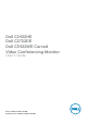
Dell C2422HE Dell C2722DE Dell C3422WE Curved Video Conferencing Monitor User’s Guide Model: C2422HE/C2722DE/C3422WE Regulatory model: C2422HEt/C2722DEt/C3422WEt
NOTE: A NOTE indicates important information that helps you make better use of your computer. CAUTION: A CAUTION indicates potential damage to hardware or loss of data if instructions are not followed. WARNING: A WARNING indicates a potential for property damage, personal injury, or death. Copyright © 2020 - 2021 Dell Inc. or its subsidiaries. All rights reserved. Dell, EMC, and other trademarks are trademarks of Dell Inc. or its subsidiaries. Other trademarks may be trademarks of their respective owners.
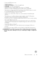
Contents Safety instructions . . . . . . . . . . . . . . . . . . . . . . . . . . . . . 6 About your monitor . . . . . . . . . . . . . . . . . . . . . . . . . . . . . 7 Package contents . . . . . . . . . . . . . . . . . . . . . . . . . 7 Product features . . . . . . . . . . . . . . . . . . . . . . . . . . 8 Identifying parts and controls . . . . . . . . . . . . . . . . . . 10 Front view . . . . . . . . . . . . . . . . . .
Tilt, swivel and vertical extension . . . . . . . . . . . . . . . . . . . . . . 42 Rotating the Display (C2422HE/C2722DE only) . . . . . . . . .43 Configuring the display settings on your computer after rotation (C2422HE/C2722DE only) . . . . . . . . . . . . . . . .44 Operating the monitor webcam . . . . . . . . . . . . . . . . . 45 Connecting your monitor . . . . . . . . . . . . . . . . . . . . .
Troubleshooting . . . . . . . . . . . . . . . . . . . . . . . . . . . . . . . 104 Self-test . . . . . . . . . . . . . . . . . . . . . . . . . . . . . 104 Built-in diagnostics . . . . . . . . . . . . . . . . . . . . . . . 105 Common Problems . . . . . . . . . . . . . . . . . . . . . . . 106 Product specific problems . . . . . . . . . . . . . . . . . . .
Safety instructions WARNING: Use of controls, adjustments, or procedures other than those specified in this documentation may result in exposure to shock, electrical hazards, and/or mechanical hazards. • Place the monitor on a solid surface and handle it carefully. The screen is fragile and can be damaged if dropped or hit sharply. • Always be sure that your monitor is electrically rated to operate with the AC power available in your location. • Keep the monitor in room temperature.
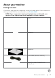
About your monitor Package contents Your monitor ships with the components shown in the table below. If any component is missing, contact Dell. For more information, see Contact Dell. NOTE: Some components may be optional and may not ship with your monitor. Some features may not be available in certain countries.
USB 3.2 Gen1 Type-A to Type-B upstream cable USB Type-C cable (C to C) • Quick Setup Guide • Safety, Environmental, and Regulatory Information Product features The Dell C2422HE/C2722DE/C3422WE monitor has an active matrix, Thin-Film Transistor (TFT), Liquid Crystal Display (LCD), and LED backlight. The monitor features include: • C2422HE: 60.47 cm (23.8 in.) active area display (Measured diagonally) 1920 x 1080 (16:9) resolution, plus full-screen support for lower resolutions. • C2722DE: 68.47 cm (27.
• • • • • • • Power and OSD buttons lock. Security lock slot. C2422HE/C2722DE: ≤ 0.3 W in Standby Mode. C3422WE: ≤ 0.5 W in Standby Mode. Supports Picture by Picture (PBP) Select mode on C3422WE. Allow user to switch USB KVM function in PBP mode on C3422WE. The monitor is designed with Dell Power Button Sync (DPBS) feature to control PC system power state from monitor power button.* • Premium Panel Exchange for peace of mind.
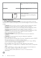
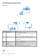
Identifying parts and controls Front view 1 2 3 45 6 7 8 9 10 11 12 Label 1,6 Description Microphones 3 Webcam lens 2,4 5 IR LED Webcam LED indicator Built-in speakers 7 10 | About your monitor 7 13 Use Monitor microphones (Mic). Mic is enabled when the webcam & Mic module is popped up. Mic is disabled when the module is retracted. Transmits your image in a video conference. Webcam is enabled when the webcam & mic module is popped up. Webcam is disabled when the module is retracted.
8 Teams button & LED 9 Hookswitch & LED 10 Volume down & LED 11 Volume up & LED 12 Microphone mute & LED 13 Power LED indicator LED will light in static white when Microsoft Teams® is signed in and running. LED will blink when there is a Teams notification. Short press on the button to bring up Teams and open notification. Ensure that the Teams application is signed in and is already running at the background.
Back view 1 2 3 4 5 Label Description 1 VESA mounting holes (100 mm x 100 mm-behind attached VESA cover) 2 Regulatory label 3 Stand release button 4 Power On/Off button 5 Joystick 6 Mac address, Barcode, serial number, and Service Tag label 7 Cable-management slot 12 | 7 6 About your monitor Use Wall mount monitor using VESAcompatible wall mount kit (100 mm x 100 mm). Lists the regulatory approvals. Releases stand from the monitor. To turn the monitor on or off.
Bottom view 9 14 1 2 Label 1 2 3 4 5 6 7 3 4 5 6 7 8 9 10 11 12 13 Description Security lock slot Power connector HDMI port DisplayPort in USB Type-C upstream/ DisplayPort Use Secures monitor with security cable lock (sold separately). Connect the power cable. Connect your computer with the HDMI cable. Connect your computer with the DisplayPort cable. Connect to your computer using the USB Type-C cable. The USB Type-C port offer the fastest transfer rate (USB 3.
8,9,11 super speed USB Connect your USB device. You can use these ports only 5 Gbps (USB 3.2 after you have connected the USB cable (Type-A to Type-B or Type-C to Type-C) from the computer to the Gen1) (3) monitor. Port with battery icon supports Battery Charging Rev. 1.2. 10 RJ-45 connector Connect Internet. You can surf Internet via RJ45 only after you have connected the USB cable(Type-A to Type-B or Type-C to Type-C) from the computer to the monitor.
Area Pixel pitch Pixel per inch (PPI) Viewing angle Horizontal Vertical Brightness Contrast ratio Curvature (Only for C3422WE) Display screen coating Backlight Response Time (Gray to Gray) Color depth Color gamut2 156246.28 mm2 (242.18 in.2) 0.2745(H) mm x 0.2745 (V) mm 92.56 200301.75 mm2 (310.47 in.2) 0.2331 (H) mm x 0.2331 (V) mm 108.79 267773.04 mm2 (415.05 in.2) 0.2325(H) mm x 0.2325(V) mm 109.
Connectivity • 1 x DP 1.2 • 1 x DP 1.4 • 1 x DP 1.2 (HDCP1.4) (HDCP1.4) (HDCP2.2) • 1 x HDMI1 .4 • 1 x HDMI1 .4 • 1 x HDMI2.0 (HDCP1.4) (HDCP1.4) (HDCP2.2) • 1 x USB Type-B (USB 3.2 Gen 1 upstream port) • 1 x USB Type-C (Alternate mode with DisplayPort 1.4/1.2, USB 3.2 Gen 1 upstream port, Power Delivery PD up to 90 W) • 1 x USB Type-C downstream (15 W), USB 3.2 Gen 1 (5 Gbps) • 1 x DP (Out) with MST (only for C2422HE/C2722DE) • 2 x super speed USB 5 Gbps (USB 3.
Resolution specifications Model C2422HE C2722DE C3422WE Horizontal scan range Vertical scan range Maximum preset resolution Video display capabilities (HDMI & DP & USB Type-C alternate mode) 30 kHz to 83 kHz 30 kHz to 90 kHz 30 kHz to 90 kHz 2560 x 1440 at 60 Hz 3440 x 1440 at 60 Hz 56 Hz to 76 Hz 1920 x 1080 at 60 Hz 480i, 480p, 576i, 560p, 720p, 1080i, 1080p About your monitor | 17
Preset display modes C2422HE Display mode VESA, 720 x 400 VESA, 640 x 480 VESA, 640 x 480 VESA, 800 x 600 VESA, 800 x 600 VESA, 1024 x 768 VESA, 1024 x 768 VESA, 1152 x 864 VESA, 1280 x 1024 VESA,1280 x 1024 VESA, 1600 x 900 VESA, 1920 x 1080 18 | Horizontal frequency (kHz) 31.47 31.47 37.50 37.88 46.88 48.36 60.02 67.50 64.0 80.0 55.99 67.50 About your monitor Vertical frequency (Hz) 70 60 75 60 75 60 75 75 60 75 60 60 Pixel clock (MHz) 28.32 25.17 31.5 40 49.5 65 78.75 108 108 135 118.25 148.
C2722DE Display Mode Horizontal Frequency (kHz) Vertical Frequency (Hz) Pixel Clock (MHz) VESA, 720 x 400 VESA, 640 x 480 VESA, 640 x 480 VESA, 800 x 600 VESA, 800 x 600 VESA, 1024 x 768 VESA, 1024 x 768 VESA, 1152 x 864 VESA, 1280 x 1024 VESA, 1280 x 1024 VESA, 1600 x 1200 VESA, 1920 x 1080 VESA, 2048 x 1080 VESA, 2048 x 1080 VESA, 2560 x 1440 31.50 31.50 37.50 37.90 46.90 48.40 60.0 67.50 64.0 80.0 75.0 67.50 58.23 66.58 88.80 70.0 60.0 75.0 60.30 75.0 60.0 75.0 75.0 60.0 75.0 60.0 60.0 26.37 60.
C3422WE Display Mode Horizontal Frequency (kHz) Vertical Frequency (Hz) Pixel Clock (MHz) VESA, 720 x 400 VESA, 640 x 480 VESA, 640 x 480 VESA, 800 x 600 VESA, 800 x 600 VESA, 1024 x 768 VESA, 1024 x 768 VESA, 1152 x 864 VESA, 1280 x 1024 VESA, 1280 x 1024 VESA, 1600 x 1200 VESA, 1920 x 1080 VESA, 2048 x 1080 VESA, 2560 x 1440 CVT, 3440 x 1440 31.50 31.50 37.50 37.90 46.90 48.40 60.0 67.50 64.0 80.0 75.0 67.50 66.58 88.80 88.81 70.0 60.0 75.0 60.30 75.0 60.0 75.0 75.0 60.0 75.0 60.0 60.0 60.0 60.0 60.
DP Multi-Stream Transport (MST) Modes C2422HE MST Source Monitor Maximum number of external monitors that can be supported 1920 x 1080 at 60 Hz 1920 x 1080 at 60 Hz 3 NOTE: Maximum external monitor resolution supported is 1920 x 1080 at 60 Hz only. C2722DE MST Source Monitor Maximum number of external monitors that can be supported 2560 x 1440 at 60 Hz 2560 x 1440 at 60 Hz 1 NOTE: Maximum external monitor resolution supported is 2560 x 1440 at 60 Hz only.
Unified Communications (UC) Platform Compatibility List The table below highlights the call functions that work on the Dell Video Conferencing Monitor – C2422HE, C2722DE and C3422WE when using the following UC platforms#.
Electrical specifications Model Video input signals C2422HE C2722DE • Digital video signal for each differential line Per differential line at 100 ohm impedance • DP/HDMI/USB Type-C signal input support Input voltage/ 100-240 VAC / 50 or 100-240 VAC / 50 or frequency/ 60 Hz ± 3 Hz / 2.3 A 60 Hz ± 3 Hz / 2.5 A current (maximum) (maximum) Inrush current 120 V: 42 A (Max.) 240 V: 80 A (Max.) Power 0.2 W (Off Mode)1 0.2 W (Off Mode)1 Consumption 0.2 W (Standby 0.3 W (Standby Mode)1 Mode)1 1 18 W (On Mode) 26.
Webcam – microphone specifications Lens Field of view (horizontal) 75.4° for 2560 x 1920 Focus mode Fixed Focus Focus area 35 cm~1.5 m Focusing distance (normal mode) 70 cm Image Sensor Active array size 5 mega-pixel Video Specification Video frame rate 1920 x 1080 (Full HD)- up to 30 frames per second Audio Specification Microphone type Digital microphone x 2 Interface USB 2.0 High Speed Power Supply 3.
Dimensions (with stand) Height (extended) 544.08 mm (21.40 in.) Height (compressed) 404.08 mm (15.90 in.) 565.57 mm (22.30 in.) 576.20 mm (22.68 in.) 445.57 mm (17.54 in.) 456.20 mm ( 17.96 in.) Width 538.64 mm (21.21 in.) 612.34 mm (24.11 in.) 815.85 mm (32.10 in.) Depth 185.00 mm (7.30 in.) 234.95 mm (9.30 in.) 230.00 mm (9.10 in.) Dimensions (without stand) Height 383.15 mm (13.90 in.) 425.43 mm (16.75 in.) 434.43 mm (17.08 in.) Width 538.64 mm (21.21 in.) 612.34 mm (24.11 in.) 815.
Environmental characteristics Compliant Standards • ENERGY STAR certified Monitor. • EPEAT registered where applicable. EPEAT registration varies by country. See https://www.epeat.net for registration status by country. • TCO and TCO Edge Certified Displays. • RoHS Compliant. • BFR/PVC Free monitor (excluding external cables). • Meets NFPA 99 leakage current requirements. • Arsenic-Free glass and Mercury-Free for the panel only.
Pin assignments DP port (in) Pin number 20-pin side of the connected signal cable 1 ML3(n) 2 GND 3 ML3(p) 4 ML2(n) 5 GND 6 ML2(p) 7 ML1(n) 8 GND 9 ML1(p) 10 ML0(n) 11 GND 12 ML0(p) 13 CONFIG1 14 CONFIG2 15 AUX CH (p) 16 GND 17 AUX CH (n) 18 Hot Plug Detect 19 Return 20 DP_PWR About your monitor | 27
DP port (out) Pin number 20-pin side of the connected signal cable 1 ML0(p) 2 GND 3 ML0(n) 4 ML1(p) 5 GND 6 ML1(n) 7 ML2(p) 8 GND 9 ML2(n) 10 ML3(p) 11 GND 12 ML3(n) 13 CONFIG1 14 CONFIG2 15 AUX CH(p) 16 GND 17 AUX CH(n) 18 Hot Plug Detect 19 Return 20 DP_PWR 28 | About your monitor
HDMI port Pin number 19-pin side of the connected signal cable 1 TMDS DATA 2+ 2 TMDS DATA 2 SHIELD 3 TMDS DATA 2- 4 TMDS DATA 1+ 5 TMDS DATA 1 SHIELD 6 TMDS DATA 1- 7 TMDS DATA 0+ 8 TMDS DATA 0 SHIELD 9 TMDS DATA 0- 10 TMDS CLOCK+ 11 TMDS CLOCK SHIELD 12 TMDS CLOCK- 13 CEC 14 Reserved (N.C.
USB Type-C port Pin Signal Pin Signal A1 GND B12 GND A2 SSTXp1 B11 SSRXp1 A3 SSTXn1 B10 SSRXn1 A4 VBUS B9 VBUS A5 CC1 B8 SBU2 A6 Dp1 B7 Dn1 A7 Dn1 B6 Dp1 A8 SBU1 B5 CC2 A9 VBUS B4 VBUS A10 SSRXn2 B3 SSTXn2 A11 SSRXp2 B2 SSTXp2 A12 GND B1 GND 30 | About your monitor
Universal Serial Bus (USB) This section gives you information about the USB ports available on your monitor. NOTE: Up to 2 A on USB downstream port (port with battery icon) with BC 1.2 compliance devices; up to 0.9 A on the other 2 USB downstream ports; icon) with 5 V/3 A Up to 3 A on USB Type-C downstream port (port with compliance devices. Your computer has the following USB ports: • 2 upstream - at rear. • 4 downstream - 2 at bottom, 2 at rear.
RJ45 port (connector side) Pin Signal Pin Signal 1 TD1 + 8 TD3 - 2 TD1 - 9 TD4 + 3 TD2 + 10 TD4 - 4 TD2 - 11 GREEN_ORANGE 5 CT 12 GREEN_ORANGE 6 CT 13 GREEN 7 TD3 + 14 GREEN GREEN RJ45 CABLE SIDE PHY SIDE GREEN ORANGE 2kV, 1000pF SHIELD GROUND Driver installation Install the Realtek USB GBE Ethernet Controller Driver available for your system. This is available for download at https://www.dell.com/support under the “Driver and download” section.
RJ45 Connector LED status: Right LED Left LED LED Color Description Right LED Amber or Green Speed indicator: • Amber On - 1000 Mbps • Green On - 100 Mbps • Off - 10 Mbps Left LED Green Link / Activity indicator: • Blinking - Activity on the port. • Green On - Link is being established. • Off - Link is not established. NOTE: RJ45 cable is non in-box standard accessory.
Plug-and-Play You can install the monitor in any Plug-and-Play-compatible system. The monitor automatically provides the computer system with its extended display identification data (EDID) using display data channel (DDC) protocols so the computer can configure itself and optimize the monitor settings. Most monitor installations are automatic; you can select different settings if desired. For more information about changing the monitor settings, see Operating the Monitor.
Ergonomics CAUTION: Improper or prolonged usage of keyboard may result in injury. CAUTION: Viewing the monitor screen for extended periods of time may result in eye strain. For comfort and efficiency, observe the following guidelines when setting up and using your computer workstation: • Position your computer so that the monitor and keyboard are directly in front of you as you work. Special shelves are commercially available to help you correctly position your keyboard.
• Keep the area under your desk clear of obstructions and cables or power cords that may interfere with comfortable seating or present a potential trip hazard.
Handling and moving your display To ensure the monitor is handled safely when lifting or moving it, follow the guidelines mentioned below: • Before moving or lifting the monitor, turn off your computer and the monitor. • Disconnect all cables from the monitor. • Place the monitor in the original box with the original packing materials. • Hold the bottom edge and the side of the monitor firmly without applying excessive pressure when lifting or moving the monitor.
• When lifting or moving the monitor, do not turn the monitor upside down while holding the stand base or stand riser. This may result in accidental damage to the monitor or cause personal injury. Maintenance guidelines Cleaning your monitor WARNING: Before cleaning the monitor, unplug the monitor power cable from the electrical outlet. CAUTION: Read and follow the Safety Instructions before cleaning the monitor.
Setting up the monitor Connecting the stand NOTE: The stand riser and stand base are detached when the monitor is shipped from the factory. NOTE: The following instructions are applicable only for the stand that was shipped with your monitor. If you are connecting a stand that you purchased from any other source, follow the set up instructions that were included with the stand. To attach the monitor stand: 1. Align and place the stand riser on the stand base. 2.
4. Open the protective cover on the monitor to access the VESA slot on the monitor. 5. Slide the tabs on the stand riser into the slots on the display back cover and lower the stand assembly to snap it into place.
6. Hold the stand riser and lift the monitor carefully, then place it on a flat surface. NOTE: Hold the stand riser firmly when lifting the monitor to avoid any accidental damage. 7. Lift the protective cover from the monitor.
Using the tilt, swivel, and vertical extension NOTE: The following instructions are applicable only for the stand that was shipped with your monitor. If you are connecting a stand that you purchased from any other source, follow the set up instructions that were included with the stand. Tilt, swivel and vertical extension With the stand attached to the monitor, you can tilt the monitor for the most comfortable viewing angle.
C3422WE 5° 120 mm 30° 30° 21° NOTE: The stand is detached when the monitor is shipped from the factory. Rotating the Display (C2422HE/C2722DE only) Before you rotate the display, extend the display vertically until the top of the stand riser and then tilt the display backwards until the maximum to avoid hitting the bottom edge of the display.
Configuring the display settings on your computer after rotation (C2422HE/C2722DE only) After you have rotated the display, complete the procedure given below to configure the display settings on your computer. NOTE: If you are using the monitor with a non-Dell computer, go to the graphics card manufacturer’s website or your computer manufacturer website for information on how to rotate the contents of your display. To configure the Display Settings: 1. Right-click on the Desktop and click Properties. 2.
Operating the monitor webcam When you want to use the monitor built-in webcam and microphone, press down on the webcam module and then release. The webcam module will pop up.
Connecting your monitor WARNING: Before you begin any of the procedures in this section, follow the Safety Instructions. To connect your monitor to the computer: 1. Turn off your computer. 2. Connect the DisplayPort or USB cable, and the USB Type-C cable from your monitor to the computer. 3. Turn on your monitor. 4. Select the correct input source from the OSD Menu on your monitor and then turn on your computer. NOTE: C2422HE/C3422WE default setting is DisplayPort 1.
Connecting the DP cable DP DP Connecting the monitor for DP Multi-Stream Transport (MST) function (C2422HE/C2722DE only) DP DP DP out DP NOTE: Supports the DP MST feature. To make use of this feature, your PC Graphics Card must be certified to at least DP1.2 with MST option. NOTE: Remove the rubber plug when using DP out connector. NOTE: It is not recommended to connect multiple C2422HE / C2722DE / C3422WE in DP MST function.
Connecting the USB cable USB USB USB Connecting the USB Type-C cable USB Type-C USB Type-C The USB Type-C port on your monitor: • Can be used as USB Type-C, DisplayPort 1.4 (C2722DE) or DisplayPort 1.2 (C2422HE/C3422WE), alternatively. • Supports USB Power Delivery (PD), with profiles up to 90 W.
Connecting the monitor for USB-C Multi-Stream Transport (MST) function (C2422HE/C2722DE only) DP in USB Type-C DP out USB Type-C NOTE: The maximum number of supported C2422HE/C2722DE via MST is subjected to the bandwith of the USB-C source. Please refer to “product specific problems –No image when using USB Type-C MST”. NOTE: Remove the rubber plug when using DP out connector. NOTE: It is not recommended to connect multiple C2422HE / C2722DE / C3422WE in DP MST function.
Dell Power Button Sync (DPBS) Your monitor is designed with Dell Power Button Sync (DPBS) feature to allow you to control PC system power state from the monitor power button. This feature is only supported with Dell platform which has built-in DPBS function, and is only supported over USB-C interface. USB Type-C USB Type-C To make sure the DPBS function works for the first time, perform the following steps on the DPBS supported platform in the Control Panel first.
3. Go to System Settings 4. In the drop-down menu of When I press the power button, there are a few options for selection namely Do nothing/Sleep/Hibernate/Shut down, and you can select Sleep/Hibernate/Shut down. NOTE: Do not select Do nothing, otherwise monitor power button cannot sync with PC system power state.
Connecting the monitor for DPBS for the first time USB-C Initial monitor power state(OFF) Initial system power state(OFF) USB-C For the first time setting up the DPBS function: 1. Make sure both the PC and monitor is OFF. 2. Press the monitor power button to turn ON the monitor. 3. Connect the USB-C cable from the PC to the monitor. 4. Both the monitor and PC will turn ON normally except Dell Optiplex 7090/3090 Ultra platform. 5.
Using DPBS function Waking on the USB-C cable • When you connect the USB-C cable, the Monitor/PC state is as follows: 1 USB-C Initial monitor power state (ON or Standby) 2 New Power state of monitor (ON) New Power state of system (ON) Initial system power state (ON) USB-C Connect USB-C cable USB-C 1 USB-C Initial monitor power state (ON or Standby) 2 New Power state of monitor (ON)* New Power state of system (ON)* Initial system power state (OFF) USB-C Connect USB-C cable USB-C * Not all
• When the monitor and the PC power state are both ON, press and hold the monitor power button for 4 seconds, the screen prompt will ask if you would like to shut down the PC. USB Type-C Press and hold 4s PC will shut down Slide to shut down your PC • When the monitor and the PC power state are both ON, press and hold the monitor power button for 10 seconds, the PC will shut down.
Connecting the monitor for USB-C Multi-Stream Transport (MST) function (C2422HE/C2722DE only) in DPBS mode A PC is connected to two monitors in an initially OFF power state, and the PC system power state is in sync with Monitor 1 power button. When you press the Monitor 1 or PC power button, both the Monitor 1 and PC turns ON. Meanwhile the Monitor 2 will remain OFF. You need to manually press the power button on Monitor 2 to turn it ON.
Connecting the monitor for USB-C in DPBS mode The Dell OptiPlex 7090 Ultra platform has two USB-C ports, so both Monitor 1 and Monitor 2 power state will sync with the PC. While the PC and two monitors are in an initially ON power state, by pressing the power button on Monitor 1 or Monitor 2 will turn OFF the PC, Monitor 1, and Monitor 2.
Make sure to set USB-C Charging to On in Off Mode. While the PC and two monitors are in an initially OFF power state, by pressing the power button on Monitor 1 or Monitor 2 will turn ON the PC, Monitor 1, and Monitor 2.
Organizing your cables After attaching all necessary cables to your monitor and computer, (see Connecting Your Monitor for cable attachment) organize all cables as shown above. Securing your monitor using Kensington lock (optional) The security lock slot is located at the bottom of the monitor. (See Security lock slot) For more information on using the Kensington lock (purchased separately), see the documentation that is shipped with the lock.
Removing the monitor stand CAUTION: To prevent scratches on the LCD screen when removing the stand, ensure that the monitor is placed on a soft, clean surface. NOTE: The following instructions are applicable only for the stand that was shipped with your monitor. If you are connecting a stand that you purchased from any other source, follow the set up instructions that were included with the stand. To remove the stand: 1. Place the monitor on a soft cloth or cushion. 2.
Wall mounting (Optional) NOTE: Use M4 x 11 mm screws to connect the monitor to the wallmounting kit. Refer to the instructions that come with the VESA-compatible wall mounting kit. 1. Place the monitor on a soft cloth or cushion on a stable flat table. 2. Remove the stand. 3. Use a Phillips crosshead screwdriver to remove the four screws securing the plastic cover. 4. Attach the mounting bracket from the wall mounting kit to the monitor. 5.
Operating the monitor Power on the monitor Press the button to turn on the monitor. Using the joystick control Use the joystick control on the rear of the monitor to make OSD adjustments. 1. Press the joystick button to launch the OSD main menu. 2. Move the joystick up/down/left/right to toggle between options. 3. Press the joystick button again to confirm the settings and exit. Joystick Description • When the OSD menu is on, press the button to confirm the selection or save the settings.
Using the rear-panel controls Use the joystick control on the rear of the monitor to adjust the display settings. As you use the button to adjust the settings, an OSD shows the numeric values of each feature as they change. Display Info The following table describes the rear-panel buttons: Options 1 Shortcut key: Menu Description Use this Menu button to launch the on-screen display (OSD) and select the OSD menu. See Accessing the menu system Use this button to choose from a list of Display Info.
Using the OSD lock function You can lock the front-panel control buttons to prevent access to the OSD menu and/ or power button. Use the Lock menu to lock the button(s). 1. Select one of the following options. 24/27/34 Monitor Brightness/Contrast Language Input Source Rotation Color Transparency Display Timer PIP/PBP Lock Menu Buttons USB Reset Menu Power Button Audio Menu + Power Buttons Menu Disable Personalize Others Exit 2. The following message appears.
Use the Joystick to lock the button(s). Press the left directional navigation of Joystick for four seconds, a menu appears on the screen. Select Option: Select one of the following options: Options Description 1 Select this option to lock OSD menu function. Menu Button lock 2 Power Button lock Use this option to lock power button. This will prevent the user to turn off the monitor using the power button. Use this option to lock OSD menu and power button to turn off the monitor.
To unlock the button(s). Press the left directional navigation of Joystick for four seconds until a menu appears on the screen. The following table describes the options to unlock the front-panel control buttons. Select Option: Options Description 1 Use this option to unlock OSD menu function. Menu Button unlock Use this option to unlock power button to turn off the monitor. 2 Power Button unlock Use this option to unlock OSD menu and power button to turn off the monitor.
Front‑panel button Use the buttons on the front of the monitor to adjust the image settings. Front Panel Description 1 Use the Up (increase) and Down (decrease) buttons to adjust items in the OSD menu. Up Down Use the Previous button to go back to the previous menu. 2 Previous Use the Next button to confirm your selection. 3 Next Use the Tick button to confirm your selection.
Using the On-Screen Display (OSD) Menu Accessing the menu system Icon Menu and Submenus Brightness/ Contrast Description Use this menu to activate Brightness/Contrast adjustment. 24/27/34 Monitor Brightness/Contrast Input Source Color Display PIP/PBP USB Audio Menu Personalize Others 75% 75% Exit Brightness Brightness adjusts the luminance of the backlight (minimum 0; maximum 100). Move the joystick up to increase brightness. Move the joystick down to decrease brightness.
Icon Menu and Submenus Input Source Description Use the Input Source menu to select between different video inputs that are connected to your monitor.
Icon Menu and Submenus Reset Input Source Color Description Resets all settings under the Input Source menu to the factory defaults. Use the Color menu to adjust the color setting mode. 24/27/34 Monitor Brightness/Contrast Preset Modes Standard Input Source Input Color Format RGB Color Reset Color Display PIP/PBP USB Audio Menu Personalize Others Exit Preset Modes When you select Preset Modes, you can choose Standard, Movie, Game, Warm, Cool or Custom Color from the list.
Icon Menu and Submenus Input Color Format Description • Standard: Default Color setting, This monitor uses a low blue light panel, and is certified by TUV to reduce blue light output and create a more relaxing and less stimulating image while reading content on the screen. • Movie: Ideal for movies. • Game: Ideal for most gaming applications. • Warm: Presents colors at lower color temperatures. The screen appears warmer with a red/yellow tint. • Cool: Presents colors at higher color temperatures.
Icon Menu and Submenus Saturation Reset Color Display Description Use joystick up or down to adjust the saturation from 0 to 100. NOTE: Saturation adjustment is available only for Movie and Game mode. Resets your monitor’s color settings to the factory defaults. Use the Display menu to adjust image.
Icon Menu and Submenus USB-C Prioritization (C2722DE only) Description Allows you to specify the priority to transfer the data with high resolution (High Resolution) or high speed (High Data Speed) when using the USB Type-C port/DisplayPort. NOTE: If your PC does not have a built-in battery pack and is powered directly from the monitor USB Type-C port (such as the Dell OptiPlex Ultra Desktop), changing USB-C Prioritization on the fly would interrupt the power from monitor to the PC.
Icon Menu and Submenus PIP/PBP Mode Description Adjusts the PIP or PBP (Picture by Picture) mode. You can disable this feature by selecting Off.
Icon Menu and Submenus PIP/PBP (Sub) Description Select between the different video signals that may be connected to your monitor for the PBP sub-window. Press the button to select the PBP sub-window source signal.
Icon Menu and Submenus USB Description Allows you to set the USB upstream port for the DP input signals, thus the monitor’s USB downstream port (eg. keyboard and mouse) can be used by the current input signals when you connect a computer to either one of the upstream ports. When you use only one upstream port, the connected upstream port is active.
Icon Menu and Submenus Description Audio Use the Audio Settings menu to adjust the audio settings. 24/27/34 Monitor Brightness/Contrast Volume 100 Input Source Speaker On Color Reset Audio Display PIP/PBP USB Audio Menu Personalize Others Exit Volume Allows you to increase the speaker volume. Move the joystick up and down to adjust the volume from ‘0’ to ‘100’. 76 | Speaker Select On or Off the Speaker function.
Icon Menu and Submenus Menu Description Select this option to adjust the settings of the OSD, such as the languages of the OSD, the amount of time the menu remains on screen, and so on. 24/27/34 Monitor Brightness/Contrast Language Input Source Rotation Select √ Color Transparency 20 Display Timer 20s PIP/PBP Lock Disable USB Reset Menu English Audio Menu Personalize Others Exit Language Set the OSD display to one of eight languages.
Icon Menu and Submenus Lock Description With the control buttons on the monitor locked, you can prevent people from accessing the controls. It also prevents accidental activation in multiple monitors side-by-side setup.
Icon Menu and Submenus Shortcut key 1 Shortcut key 2 Shortcut key 3 Shortcut key 4 Shortcut key 5 Power Button LED USB-C Charging 90 W Other USB Charging Fast Wakeup (C3422WE only) Reset Personalization Description Select from Preset Modes, Brightness/Contrast, Input Source, Aspect Ratio, Rotation, Display Info set as shortcut key. Allows you to set the state of the power light to save energy. Allows you to enable or disable USB-C Charging charging function during monitor power off mode.
Icon Menu and Submenus Others Description Select this option to adjust the OSD settings such as the DDC/CI, LCD conditioning, and so on. 24/27/34 Monitor Brightness/Contrast Display Info Select √ Input Source DDC/CI On Color LCD Conditioning Off Display Firmware M2T101 PIP/PBP Service Tag ABCDEFG USB Reset Others Audio Factory Reset ENERGY STAR® Menu Personalize Others Exit Display Info Displays the monitor’s current settings.
Icon Menu and Submenus LCD Conditioning Description Helps reduce minor cases of image retention. Depending on the degree of image retention, the program may take some time to run. You can enable this feature by selecting On.
OSD warning messages When the monitor does not support a particular resolution mode, you can see the following message: The current input timing is not supported by the monitor display. Please change your input timing to 1920x1080/2560x1440/3440x1440, 60Hz or any other monitor listed timing as per monitor specifications. This means that the monitor cannot synchronize with the signal that it is receiving from the computer.
If you press any button other than the power button, the following messages will appear depending on the selected input: No DP Signal form your device. Press any key on the keyboard to wake up. If there is no display, press the monitor joystick to select input source. A message is displayed while the cable supporting DP alternate mode is connected to the monitor under the following conditions: • When Auto Select for USB-C • When the USB-C cable is connected to the monitor.
When you select ‘Yes‘ to reset to default settings, the following message will appear: 24/27/34 Monitor Select ‘Yes’ to enable the following function(s): . Always on USB-C Charging . Other USB Charging Yes No When ‘Yes’ is selected, power consumption will increase. When ‘No’ is selected, it will comply with ENERGY STAR requirements. Individual settings of the functions can be changed in the Menu.
If either USB Type-C / DP / HDMI input is selected and the corresponding cable is not connected, a floating dialog box as shown below appears. No DP Cable The display will go into Standby Mode in 4 minutes. www.dell.com/C24/27/3422XE or No USB-C Cable The display will go into Standby Mode in 4 minutes. www.dell.com/C24/27/3422XE or No HDMI Cable The display will go into Standby Mode in 4 minutes. www.dell.
If the webcam is pop in (retracted) and you press the Mute button, the following message will appear: Please pop up webcam + mic module to enable your mic When the USB upstream cable is not connected, and you press the Teams/ Hookswitch/ Mute button, the following message will appear: This function is inactive. To enable it, you need to connect USB upstream to the monitor.
Setting the maximum resolution To set the maximum resolution for the monitor: In Windows 7, Windows 8 or Windows 8.1: 1. For Windows 8 or Windows 8.1 only, select the Desktop tile to switch to classic desktop. For Windows Vista and Windows 7, skip this step. 2. Right-click on the desktop and click Screen Resolution. 3. Click the Dropdown list of the Screen Resolution and select 1920 x 1080 (C2422HE) / 2560 x 1440 (C2722DE) / 3440 x 1440 (C3422WE). 4. Click OK. In Windows 10: 1.
Setting the KVM USB Switch To set the KVM USB Switch as Shortcut Key for the monitor: 1. Press the joystick button to launch the OSD main menu. 2. Move the joystick to select Personalize.
The following are illustrations of several connection scenarios and their USB Selection menu settings, as illustrated in corresponding color frames. 1. When connecting HDMI + USB-B to computer 1 and DP + USB A to C to computer 2: 1 1 HDMI 2 4 USB-B 3 2 DP USB A to C 3 4 NOTE: The USB Type-C connection currently supports only data transfer. Ensure USB Selection for HDMI is set to USB-B and DP is set to USB-C 90 W.
2. When connecting HDMI + USB-B to computer 1 and USB Type-C to computer 2: 1 HDMI 1 2 3 2 USB-B USB Type-C 3 NOTE: The USB Type-C connection currently supports video and data transfer. Ensure USB Selection for HDMI is set to USB-B.
Setting the Auto KVM You can follow below instruction to set up Auto KVM for your monitor: 1. Ensure that PIP/PBP Mode is Off. 24/27/34 Monitor Brightness/Contrast PIP/PBP Mode Off Input Source PIP/PBP (Sub) USB-C Color USB Switch Display Video Swap PIP/PBP Audio Main USB Contrast (Sub) 75 90 W Audio Menu Personalize Others Exit NOTE: This PIP/PBP function is for C3422WE only. 2. Ensure that Auto Select is On and Auto Select for USB-C is Yes.
24/27/34 Monitor Brightness/Contrast USB-C Input Source DP Color HDMI Display Auto Select Prompt for Multiple Inputs PIP/PBP Auto Select for USB-C Yes USB Rename Inputs No Audio Reset Input Source 90W Menu Personalize Others Exit 3. Ensure that the USB ports and the video inputs are paired accordingly.
Setting up Windows Hello In Windows® 10: Click Windows start menu, click Settings. Click Accounts. Click Sign-in options. You must set up a PIN before you can enroll in Windows Hello.
Click Add under PIN enter to Set up a PIN. Enter New PIN and Confirm PIN, and thenclick OK. Once you’ve done that, the options to set up Windows Hello will unlock. Click Set up under Windows Hello, enter to Windows Hello setup.
The following message is displayed, click Get started. Keep looking directly at your screen and position yourself so that your face is in the center of the frame that appears on screen. The webcam will then register your face.
When the following message is displayed, click Close to exit Windows Hello setup. Once you have set up, you have another option to improve the recognition. Click Improve recognition if necessary.
Setting up the monitor webcam as default setting When using a notebook with built-in webcam to connect this monitor, in the device manager interface, you can find the notebook built-in webcam and the monitor webcam. Normally, they are in enable status, and the default setting is using notebook built-in webcam. If you want to set up the monitor webcam as default setting, you need disable the notebook built-in webcam.
Click Details > Property and select Hardware Ids.
The Value will show the detail hardware ids of this Dell Monitor IR Webcam. The hardware ids of the notebook built-in webcam and the monitor webcam are different. For C2422HE/C2722DE/C3422WE, the monitor webcam hardware ids will show as below: Right click the PC/Notebook webcam which has different hardware ids , and then click Disable.
The following message is displayed: Click Yes. The notebook webcam is now disabled and the monitor webcam will be used as the default setting. Restart the notebook.
Setting up the monitor speaker as default setting When your computer connects multiple speakers, if you want to set up the monitor speaker as default setting, please follow below instructions: Right-click Volume in the Windows task bar notification area. Click Playback devices enter to Sound setting interface. If only the HDMI or DP cable is connected from your monitor to the computer, only one speaker named DELL C2422HE/C2722DE/C3422WE from the monitor will show in the Sound setting interface.
Click DELL C2422HE/C2722DE/C3422WE, and then click Set Default, the monitor speaker will be used as the default setting. Click OK to exit the Sound setting. If the USB cable and the HDMI or DP cable are connected from monitor to the computer, two audio paths named DELL C2422HE/C2722DE/C3422WE and Echo Cancelling Speakerphone (C2422HE/C2722DE/C3422WE) from the monitor will show in the Sound setting interface.
• • Echo Cancelling Speakerphone (C2422HE/C2722DE/C3422WE) audio path is where audio streams through USB. This is either through USB-C to USB-C cable or USB-A to USB-B cable. As the microphone path streams from monitor back to PC through USB, this selection is required for VolP/UC conference applications. Audio Recording and Playback will work under this selection. DELL C2422HE/C2722DE/C3422WE audio path is where audio streams through HDMI/ DP/ DP alternate mode.
Troubleshooting WARNING: Before you begin any of the procedures in this section, follow the Safety Instructions. Self-test Your monitor provides a self-test feature that allows you to check whether your monitor is functioning properly. If your monitor and computer are properly connected but the monitor screen remains dark, run the monitor self-test by performing the following steps: 1. Turn off both your computer and the monitor. 2. Unplug the video cable from the back of the computer.
Built-in diagnostics Your monitor has a built-in diagnostic tool that helps you determine if the screen abnormality you are experiencing is an inherent problem with your monitor, or with your computer and video card. Display Info To run the built-in diagnostics: 1. Ensure that the screen is clean (no dust particles on the surface of the screen). 2. Press and hold Up or Down or Left or Right direction for four seconds until a menu appears on the screen. 3.
Common Problems The following table contains general information about common monitor problems you might encounter and the possible solutions: Common Symptoms No Video/ Power LED off What you experience No picture Possible solutions • Ensure that the video cable connecting the monitor and the computer is properly connected and secure. • Verify that the power outlet is functioning properly using any other electrical equipment. • Ensure that the power button is depressed fully.
Common Symptoms Safety Related Issues Intermittent Problems What you experience Visible signs of smoke or sparks Monitor malfunctions on & off Possible solutions • Do not perform any troubleshooting steps. • Contact Dell immediately. • Ensure that the video cable connecting the monitor to the computer is connected properly and is secure. • Reset the monitor to factory settings. • Perform monitor self-test feature check to determine if the intermittent problem occurs in self-test mode.
Common Symptoms Mic/Webcam does not work What you experience • Webcam module not pop up • USB cable not plug in or not select the correct USB source • Not set the monitor Mic/ webcam as the default device Possible solutions • Pop up the webcam module. • Plug in the USB Cable (Type-A to Type-B or Type-C to Type-C), and if you connect both USB-B port and USB-C port, please switch the USB source in the OSD menu. • Select the monitor Mic/webcam as the default in the PC side.
Problem What you experience The picture The picture does not fill the cannot fill the entire screen height or width of the screen Blank screen No image when using DP connection to the PC No image when using USB Type-C connection to computer, laptop, and so on Blank screen No charging when using USB Type-C connection to computer, laptop, and so on No charging Possible solutions • Due to different video formats (aspect ratio) of DVDs, the monitor may display in full screen.
Problem What you experience Intermittent charging Intermittent charging when using USB Type-C connection to computer, laptop, and so on No image when Blank screen or using USB 2nd DUT is not Type-C MST Prime mode No network connection Network dropped or Intermittent Possible solutions • Check if the maximum power consumption of device is over 90 W. • Ensure that you use only Dell approved adapter or the adapter that comes with the product. • Ensure that the USB Type-C cable is not damaged.
Problem What you experience Monitor Monitor buttons (Mute buttons (Mute / Volume down / Volume down / Volume up / / Volume up / Hookswitch) Hookswitch) not working not working with Microsoft on Microsoft Teams® App with Teams® App Chrome OS / Ubuntu Video recording Video recording not working App not working with Win 7 Possible solutions Use Microsoft Teams® App to perform the below tasks: • Call Icon to accept / hang up call • Volume down / Volume up adjustment • Mic mute / unmute • Camera on / off • Wi
Problem What you experience Ethernet port Ethernet port (RJ45) cannot (RJ45) cannot connect to connect to internet internet on Win 10 Microphone not Microphone not working or not working or not detect detect on the Voice recorder App with Intel Gen 11th CPU (Tiger Lake) platform No sound can No sound can be heard from be heard from recorded video recorded video with Intel Gen 11th CPU (Tiger Lake) platform When press either Volume down/ Volume up, OSD volume bar response is lagging/delayed 112 | Whe
Problem No sound coming from the speakers What you Possible solutions experience No sound • Ensure that you have set the default playback coming from the device as Echo Cancelling Speakerphone speakers when (C2422HE/C2722DE/C3422WE) or DELL play audio/video C2422HE/C2722DE/C3422WE on your system. on your system • Turn Off the monitor, unplug the monitor power cord, replug it, and then turn On the monitor. • Reset the monitor to Factory Settings.
Problem What you experience Webcam Could not detect cannot connect Monitor camera / Webcam / Could not disconnected switch back to the PC camera Microphone is muted Microphone volume is low / sounds soft 114 | Possible solutions • Reset the monitor to Factory Settings. • Turn Off the monitor, unplug the monitor power cord, replug it, and then turn On the monitor. • Select the Monitor camera again in the Camera / Video setting of your UC conference application.
Problem Front buttons don’t work What you experience No response on the UC application when press on the buttons located on the speaker Possible solutions • Ensure that the USB upstream cable (Type-A to Type-B or Type-C to Type-C) is connected from the PC to the monitor. • Ensure that the webcam module is popped up. • For some UC platforms / applications, the Mute function works by pressing the Mute button, but the Mute Icon on the UC platform is not sync (Icon shows unmute).
Microsoft® Teams® / Skype for Business® specific problems Problem The Teams button is not working The Hookswitch button is not working The Mute button is not working Webcam no image 116 | What you Possible solutions experience Short press • Ensure that the USB upstream cable (Type-A on the Teams to Type-B or Type-C to Type-C) is connected button does not from the PC to the monitor.
Problem Webcam being occupied What you experience Webcam being occupied and can’t be used Possible solutions • Ensure that the webcam module is popped up. • Avoid running multiple conference softwares at the same time. While you are using ‘conference software A’, close the other ‘conference software B’.
Universal Serial Bus (USB) specific problems Specific Symptoms USB interface is not working What you experience USB peripherals are not working Possible solutions • Check that your display is turned ON. • Reconnect the upstream cable to your computer. • Reconnect the USB peripherals (downstream connector). • Turn off the monitor and turn it on again. • Reboot the computer. • Certain USB devices such as portable hard drives require higher power source; connect the drive to the computer directly.
Appendix FCC notices (U.S. only) and other regulatory information For FCC notices and other regulatory information, see the regulatory compliance website located at https://www.dell.com/regulatory_compliance. Contacting Dell For customers in the United States, call 800-WWW-DELL (800-999-3355). NOTE: If you do not have an active Internet connection, you can find contact information on your purchase invoice, packing slip, bill, or Dell product catalog.