Dell Vostro 270s Owner’s Manual Regulatory Model: D06S Regulatory Type: D06S001
Notes, Cautions, and Warnings NOTE: A NOTE indicates important information that helps you make better use of your computer. CAUTION: A CAUTION indicates either potential damage to hardware or loss of data and tells you how to avoid the problem. WARNING: A WARNING indicates a potential for property damage, personal injury, or death. © 2012 Dell Inc.
Contents Notes, Cautions, and Warnings...................................................................................................2 1 Working on Your Computer.......................................................................................................5 Before Working Inside Your Computer.....................................................................................................................5 Turning Off Your Computer...............................................................
Installing the System Board....................................................................................................................................21 Removing the Power-Supply Unit...........................................................................................................................22 Installing the Power-Supply Unit............................................................................................................................22 3 System Setup....................
Working on Your Computer 1 Before Working Inside Your Computer Use the following safety guidelines to help protect your computer from potential damage and to help to ensure your personal safety. Unless otherwise noted, each procedure included in this document assumes that the following conditions exist: • You have read the safety information that shipped with your computer. • A component can be replaced or--if purchased separately--installed by performing the removal procedure in reverse order.
CAUTION: Before touching anything inside your computer, ground yourself by touching an unpainted metal surface, such as the metal at the back of the computer. While you work, periodically touch an unpainted metal surface to dissipate static electricity, which could harm internal components. Turning Off Your Computer CAUTION: To avoid losing data, save and close all open files and exit all open programs before you turn off your computer. 1.
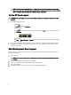
Removing and Installing Components 2 This section provides detailed information on how to remove or install the components from your computer. Recommended Tools The procedures in this document may require the following tools: • Small flat-blade screwdriver • Phillips screwdriver • Small plastic scribe Removing the Cover 1. Follow the procedures in Before Working Inside Your Computer. 2.
Installing the Cover 1. Align the cover along its tabs on the chassis and slide the cover to its original position. 2. Tighten the screws to secure the cover to the computer. 3. Follow the procedures in After Working Inside Your Computer. Removing the Front Bezel 1. Follow the procedures in Before Working Inside Your Computer. 2. Remove the cover. 3. Pry the front panel retention clips away from the chassis located at the edge of front bezel. 4.
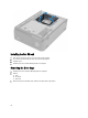
Installing the Front Bezel 1. Insert the hooks along the bottom edge of the front bezel into the slots on the chassis front. 2. Rotate the bezel toward the computer to engage the front-panel retention clips until they click into place. 3. Install the cover. 4. Follow the procedures in After Working Inside Your Computer. Removing the Fan Shroud 1. Follow the procedures in Before Working Inside Your Computer. 2. Remove the cover. 3.
Installing the Fan Shroud 1. Place the fan shroud over the processor fan and heat-sink assembly. 2. Press the fan shroud until the tabs on the fan shroud snap into place. 3. Install the cover. 4. Follow the procedures in After Working Inside Your Computer. Removing the Drive Cage 1. Follow the procedures in Before Working Inside Your Computer. 2. Remove: a) cover b) fan shroud c) front bezel 3. 10 Disconnect the power and data cables from the hard drive and the optical drive.
4. Remove the screws that secure the drive cage and lift the drive cage to remove it from the computer.
Installing the Drive Cage 1. Tighten the screws to secure the drive cage to the computer. 2. Connect the data cable and power cable to the back of the hard drive and the optical drive. 3. Install: a) front bezel b) fan shroud c) cover 4. Follow the procedures in After Working Inside Your Computer. Removing the Optical Drive 1. Follow the procedures in Before Working Inside Your Computer. 2. Remove: a) b) c) d) 3.
a) b) c) d) 5. drive cage front bezel fan shroud cover Follow the procedures in After Working Inside Your Computer. Removing the Hard Drive 1. Follow the procedures in Before Working Inside Your Computer. 2. Remove: a) b) c) d) 3. cover fan shroud front bezel drive cage Remove the screws that secure the hard drive to the drive cage and slide the hard drive out of the drive cage. Installing the Hard drive 1. Slide the hard drive into the drive cage. 2.
5. Follow the procedures in After Working Inside Your Computer. Removing the Expansion Card 1. Follow the procedures in Before Working Inside Your Computer. 2. Remove: a) cover. b) fan shroud. 3. Remove the screw that secures the expansion card to the chassis. Press down the securing tab, grasp the card and ease it out of its connector. Installing the Expansion Card 1. Insert the expansion card into it's connector on the system board and press down until it is securely in place. 2.
Installing the Coin-Cell Battery 1. Place the coin-cell battery into its slot on the system board. 2. Press the coin-cell battery downward until the release latch springs back into place and secures it. 3. Install : a) drive cage b) fan shroud c) cover 4. Follow the procedures in After Working Inside Your Computer. Removing the Memory 1. Follow the procedures in Before Working Inside Your Computer. 2. Remove: a) cover. b) fan shroud c) drive cage 3.
a) b) c) d) 3. cover fan shroud front bezel drive cage Disconnect the power-switch cable from the system board and remove the cables from their routing channels. Press the power-switch tabs to release the power switch from the front panel and slide the power switch along with its cable through the slot on the front panel. Installing the Power Switch 1. Slide the power-switch along its cable through the slot on the front panel. 2. Align and push the power-switch tabs into the slots on the front panel.
Installing the Heat-Sink Assembly 1. Align the captive screws on the heat-sink assembly with the screw holes on the system board. 2. Tighten the captive screws to secure heat-sink assembly to the system board. 3. Connect the fan cable to the system board. 4. Install: a) fan shroud. b) cover. 5. Follow the procedures in After Working Inside Your Computer. Removing the Input/Output (I/O) Panel 1. Follow the procedures in Before Working Inside Your Computer. 2. Remove: a) b) c) d) e) 3.
4. Remove the I/O panel cables from the routing channels on the chassis. 5. Remove the screw that secures the I/O panel to the front panel and slide the I/O panel toward the side and pull it out of the front panel.
Installing the I/O Panel 1. Insert the I/O panel into the slot on the front panel. 2. Slide the I/O panel to align it with the screw holes on the front panel. 3. Tighten the screw to secure the I/O panel to the front panel. 4. Route the I/O panel cables through the routing channels on the chassis. 5. Connect the I/O panel cables to the system board. 6. Install: a) b) c) d) e) 7. expansion card drive cage front bezel fan shroud cover Follow the procedures in After Working Inside Your Computer.
Installing the Processor 1. Insert the processor into the processor socket. Ensure the processor is properly seated. 2. Lower the processor cover. 3. Press the release lever down and then move it inward to secure it with the retention hook. 4. Install: a) heat-sink assembly b) fan shroud c) cover 5. Follow the procedures in After Working Inside Your Computer. Removing the System Board 1. Follow the procedures in Before Working Inside Your Computer. 2.
System Board Components Figure 1. Components Of The System Board 1. 2. 3. 4. 5. 6. 7. 8. 9. power button connector Coin-cell battery SATA connectors password reset jumper front-panel audio connector PCI Express x16 slot Mini-Card slot PCIe x1 slot 4–pin CPU power connecter 10. 11. 12. 13. 14. 15. 16. CPU Socket processor fan connector DDR DIMM memory slots (2) ATX 24–pin power connector front panel USB connector front panel USB connector CMOS jumper Installing the System Board 1.
d) e) f) g) h) 5. memory drive cage front bezel fan shroud cover Follow the procedures in After Working Inside Your Computer. Removing the Power-Supply Unit 1. Follow the procedures in Before Working Inside Your Computer. 2. Remove: a) cover b) fan shroud c) front bezel d) drive cage e) memory f) expansion card g) fan and heat sink h) processor i) system board 3. Remove the screws that secure the power-supply unit to the chassis and slide and remove the power-supply unit away from the computer.
4. Install the: a) b) c) d) e) f) g) h) i) 5. system board processor fan and heat sink expansion card memory drive cage front bezel fan shroud cover Follow the procedures in After Working Inside Your Computer.
System Setup 3 System Setup enables you to manage your computer hardware and specify BIOS‐level options.
Keys Navigation Allows you to select a value in the selected field (if applicable) or follow the link in the field. Spacebar Expands or collapses a drop‐down list, if applicable. Moves to the next focus area. NOTE: For the standard graphics browser only. Moves to the previous page till you view the main screen. Pressing in the main screen displays a message that prompts you to save any unsaved changes and restarts the system. Displays the System Setup help file.
conservation, and security features. Scroll up and down the list with the up- and down-arrow keys. As an option is highlighted, the Options Field displays the option's current and available settings. computer and make changes to your current settings. Press < Enter> to make changes to your current settings. Press to return to the Dell Diagnostics. NOTE: Not all settings listed in the Options Field are changeable.
Memory Information Memory Installed Displays the total computer memory. Memory Speed Displays the memory speed. Memory Technology Displays the type and technology. Device Information SATA 0 Displays the model number and capacity of the hard drive. SATA 1 Displays the model number and capacity of the hard drive. SATA 2 Displays the model number and capacity of the hard drive. SATA 3 Displays the model number and capacity of the hard drive. Table 5.
CPU Configuration Auto Power On Enable or disable the computer to power on automatically. You can further specify the date and time the computer power on. Default: Disabled NumLock Key Enable or disable the NumLock State light during POST. Default: On Keyboard Error Report Enable or disable the Keyboard Error Report to be displayed during POST. Default: Enabled Post Behaviour Table 6.
c) Choose from a list of all Dell products 5. On the application and drivers screen, under the Operating System drop-down list, select BIOS. 6. Identify the latest BIOS file and click Download File. 7. Select your preferred download method in the Please select your download method below window; click Download Now. The File Download window appears. 8. Click Save to save the file on your computer. 9. Click Run to install the updated BIOS settings on your computer.
13. Install the fan shroud. 14. Install the cover. 15. Follow the procedures in After Working Inside Your Computer. 16. Power-on the computer. 17. Go to the system setup, and assign a new system or setup password. Clearing CMOS 1. Follow the procedures in Before Working Inside Your Computer. 2. Remove the cover. 3. Remove the fan shroud. 4. Remove the front bezel. 5. Remove the drive cage. 6. Identify the CMOS jumper on the system board, see the System Board Components. 7.
15. Remove the fan shroud. 16. Remove the front bezel. 17. Remove the drive cage. 18. Replace the jumper on the pins 2 and 3. 19. Install the drive cage. 20. Install the front bezel. 21. Install the fan shroud. 22. Install the cover. 23. Follow the procedures in After Working Inside Your Computer. 24. Power-on the computer. System and Setup Password You can create a system password and a setup password to secure your computer.
1. In the System BIOS or System Setup screen, select System Security and press . The System Security screen appears. 2. In the System Security screen, verify that Password Status is Unlocked. 3. Select System Password , enter your system password, and press or . Use the following guidelines to assign the system password: – A password can have up to 32 characters. – The password can contain the numbers 0 through 9.
3. Identify the PSWD jumper on the system board. 4. Remove the PSWD jumper from the system board. NOTE: The existing passwords are not disabled (erased) until the computer boots without the jumper. 5. Install the cover. NOTE: If you assign a new system and/or setup password with the PSWD jumper installed, the system disables the new password(s) the next time it boots. 6. Connect the computer to the electrical outlet and power-on the computer. 7.
Diagnostics 4 If you experience a problem with your computer, run the ePSA diagnostics before contacting Dell for technical assistance. The purpose of running diagnostics is to test your computer's hardware without requiring additional equipment or risking data loss. If you are unable to fix the problem yourself, service and support personnel can use the diagnostics results to help you solve the problem.
5 Technical Specification NOTE: Offerings may vary by region. The following specifications are only those required by law to ship with your computer. For more information regarding the configuration of your computer, click Start → Help and Support and select the option to view information about your computer. Table 8.
Table 11. Video Video Video controller Integrated Intel HD Graphics Discrete one PCI Express x16, single-width, full length graphics card. Video memory Integrated 64 MB Discrete 1 GB discrete video memory NOTE: The available video memory will depend on the graphics card installed on the computer. Table 12. Ports Ports Back panel Ports Network Adapter one RJ45 port USB four 4-pin USB 2.0-compliant ports two 9-pin USB 3.
Table 15. Drives Drives Externally accessible one 5.25-inch drive bays for a Blu-ray Disc combo (optional), Blu-ray Disc Writer (optional), or DVD+/-RW Internally accessible one 3.5-inch drive bays for SATA hard drives one SATA SSD drive (optional) Table 16. Expansion Bus Expansion Bus PCI Express x1 Connectors one Connector size 36-pin PCI Express x16 Connectors one Connector size 164-pin PCI-E mini-card Connectors one Connector size 52-pin Table 17.
Environmental Operating 40 G for 2 ms with a change in velocity of 20 inches/s (51 cm/s) Non-Operating 50 G for 26 ms with a change in velocity of 320 inches/s (813 cm/s) Altitude: Operating –16 m to 3048 m (–50 to 10,000 ft) NOTE: For altitudes above 2950 feet, the maximum operating temperature is derated 1ºF/550 ft. Storage Airborne contaminant level 40 –15.20 m to 10,668 m (–50 ft to 35,000 ft) G2 or lower as defined by ISA-S71.
Contacting Dell 6 NOTE: If you do not have an active Internet connection, you can find contact information on your purchase invoice, packing slip, bill, or Dell product catalog. Dell provides several online and telephone-based support and service options. Availability varies by country and product, and some services may not be available in your area. To contact Dell for sales, technical support, or customer service issues: 1. Visit support.dell.com. 2. Select your support category. 3.