OptiPlex 3040 - Mini Tower Owner's Manual Regulatory Model: D18M Regulatory Type: D18M002
Notes, cautions, and warnings NOTE: A NOTE indicates important information that helps you make better use of your computer. CAUTION: A CAUTION indicates either potential damage to hardware or loss of data and tells you how to avoid the problem. WARNING: A WARNING indicates a potential for property damage, personal injury, or death. Copyright © 2015 Dell Inc. All rights reserved. This product is protected by U.S. and international copyright and intellectual property laws.
Contents 1 Working on your computer.................................................................................5 Before working inside your computer..................................................................................................5 Turning off your computer................................................................................................................... 6 After working inside your computer..................................................................................
Removing the coin cell battery........................................................................................................... 21 Installing the coin cell battery.............................................................................................................22 Removing the heat sink assembly...................................................................................................... 22 Installing the heat sink assembly.........................................................
Working on your computer 1 Before working inside your computer Use the following safety guidelines to help protect your computer from potential damage and to help to ensure your personal safety. Unless otherwise noted, each procedure included in this document assumes that the following conditions exist: • You have read the safety information that shipped with your computer. • A component can be replaced or--if purchased separately--installed by performing the removal procedure in reverse order.
3. Disconnect all network cables from the computer. 4. Disconnect your computer and all attached devices from their electrical outlets. 5. Press and hold the power button while the computer is unplugged to ground the system board. 6. Remove the cover. CAUTION: Before touching anything inside your computer, ground yourself by touching an unpainted metal surface, such as the metal at the back of the computer.
5. If required, verify that the computer works correctly by running Dell Diagnostics.
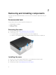
Removing and installing components This section provides detailed information on how to remove or install the components from your computer. Recommended tools The procedures in this document require the following tools: • Small flat blade screwdriver • Phillips screwdriver • Small plastic scribe Removing the cover 1. Follow the procedure in Before Working Inside Your Computer. 2. To remove the cover: a. Loosen the captive screws that secure the cover to the computer [1]. b.
Removing the bezel 1. Follow the procedure in Before Working Inside Your Computer. 2. Remove the cover. 3. To remove the front bezel: a. Lift the tabs to release the front bezel from the computer. b. Remove the front bezel from the computer. Installing the bezel 1. Insert the tabs on the bezel into the slots on the computer. 2. Press the bezel until the tabs clicks into place. 3. Install the cover. 4. Follow the procedure in After Working Inside Your Computer. Opening the front bezel door 1.
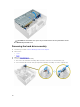
CAUTION: The front bezel door opens only to a limited extent. See the printed label for the maximum permissible level. Removing the hard drive assembly 1. Follow the procedure in Before Working Inside Your Computer. 2. Remove the: • cover 3. • bezel Open the front bezel door. 4. To remove the hard drive assembly: a. Disconnect the hard drive assembly cables from the connectors on the hard drive [1, 2]. b.
Removing the hard drive from the hard drive bracket 1. Follow the procedure in Before Working Inside Your Computer. 2. Remove the: a. cover b. bezel c. hard drive assembly 3. To remove the hard drive bracket: a. Pull one side of the hard drive bracket to disengage the pins on the bracket from the slots on the hard drive [1]. b. Lift the hard drive out of the hard drive bracket [2]. Installing the hard drive into the hard drive bracket 1.
5. • cover Follow the procedure in After Working Inside Your Computer. Removing the slim optical drive 1. Follow the procedure in Before Working Inside Your Computer. 2. Remove the: • 3. cover • bezel To remove the optical drive: a. b. c. d. Open the front bezel door. Disconnect the data cable and power cable from the connectors on the optical drive [1, 2]. Close the front bezel door [3]. Press the blue release tab [4] and slide the optical drive out of the computer [5].
Removing the optical drive (3.5-inch) 1. Follow the procedure in Before Working Inside Your Computer. 2. Remove the: • 3. cover • bezel To remove the optical drive: a. Disconnect the data cable and power cable from the connectors on the optical drive [1, 2]. b. Press the blue release tab [3] and slide the optical drive out of the optical drive bay [4]. Installing the optical drive (3.5-inch) 1. Insert the optical drive into the optical drive bay until it clicks into place. 2.
a. Disconnect the SD card reader cable from the connector on the system board [1]. b. Remove the screw that secures the SD card reader to the computer [2]. c. Lift the SD card reader out of the computer [3]. Installing the SD card reader 1. Insert the SD card reader into the slot on the system board. 2. Tighten the screw to secure the SD card reader to the system board 3. Connect the SD card reader cable to the connector on the system board. 4. Close the front bezel door. 5. Install the: a.
Installing the memory module 1. Align the notch on the memory module with the tab on the memory module connector. 2. Insert the memory module into the memory module socket. 3. Press the memory module until the memory module retention tabs click into place. 4. Close the front bezel door. 5. Install the: a. cover b. bezel 6. Follow the procedure in After Working Inside Your Computer. Removing the PCIe expansion card 1. Follow the procedure in Before Working Inside Your Computer. 2.
Installing the PCIe expansion card 1. Pull the release latch to open it. 2. Insert the PCIe expansion card to the connector on the system board. 3. Secure the PCIe expansion card by pushing the card retention latch until it clicks into place. 4. Close the release latch. 5. Close the front bezel door. 6. Install the: a. bezel b. cover 7. Follow the procedure in After Working Inside Your Computer.
3. Insert the Ethernet port card into the connector on the system board until it clicks into place. 4. Close the release latch. 5. Install the: a. bezel b. cover 6. Close the front bezel door. 7. Follow the procedure in After Working Inside Your Computer. Removing the power supply unit (PSU) 1. Follow the procedure in Before Working Inside Your Computer. 2. Remove the: • cover 3. • bezel Open the front bezel door. 4. To remove the PSU: a. b. c. d.
6. Install the: • 7. bezel • cover Follow the procedure in After Working Inside Your Computer. Removing the VGA daughter board 1. Follow the procedure in Before Working Inside Your Computer. 2. Remove the: • cover 3. • bezel Open the front bezel door 4. To remove the VGA daughter board: a. b. c. d. Remove the screws that secure the VGA connector to the computer [1]. Slide the VGA connector to release it from the computer [2].
Removing the intrusion switch 1. Follow the procedure in Before Working Inside Your Computer. 2. Remove the: • cover 3. • bezel Open the front bezel door. 4. To remove the intrusion switch: a. Disconnect the intrusion switch cable from the connector on the system board [1]. b. Unroute the intrusion switch cable from the fan grommet [2]. c. Slide the intrusion switch and lift it away from the computer [3]. Installing the intrusion switch 1. Insert the intrusion switch into the slot on the computer.
4. To remove the power switch: a. Disconnect the power switch cable from the system board [1]. b. Unroute the power switch cable from the retention clip. c. Press the release tab [2] and slide the power switch out of the computer [3]. Installing the power switch 1. Insert the power switch into the slot and press it until it clicks into place. 2. Route the power switch cable through the cable retention clip. 3. Connect the power switch cable to the connector on the system board. 4.
Installing the speaker 1. Insert the speaker into the slot and press it until it clicks into place. 2. Open the front bezel door. 3. Connect the speaker cable to the connector on the system board. 4. Close the front bezel door. 5. Install the: a. bezel b. cover 6. Follow the procedure in After Working Inside Your Computer. Removing the coin cell battery 1. Follow the procedure in Before Working Inside Your Computer. 2. Remove the: • cover 3. • bezel Open the front bezel door. 4.
Installing the coin cell battery 1. Hold the coin cell battery with the "+" sign facing up and slide it under the securing tabs at the positive side of the connector. 2. Press the battery into the connector until it locks into place. 3. Close the front bezel door. 4. Install the: • 5. bezel • cover Follow the procedure in After Working Inside Your Computer. Removing the heat sink assembly 1. Follow the procedure in Before Working Inside Your Computer. 2. Remove the: • cover 3.
• 6. bezel • cover Follow the procedure in After Working Inside Your Computer. Removing the processor 1. Follow the procedure in Before Working Inside Your Computer. 2. Remove the: • cover 3. • bezel Open the front bezel door. 4. Remove the heat sink assembly. 5. To remove the processor: a. Release the socket lever by pushing the lever down and out from under the tab on the processor shield [1]. b. Lift the lever upward and lift the processor shield [2]. c.
Removing the system fan 1. Follow the procedure in Before Working Inside Your Computer. 2. Remove the: • cover 3. • bezel Open the front bezel door. 4. To remove the system fan: a. Disconnect the system fan cable from the connector on the system board [1]. b. Stretch the grommets securing the fan to the computer to ease the removal of the fan [2]. c. Slide the system fan out of the computer [3]. Installing the system fan 1.
Removing the system board 1. Follow the procedure in Before Working Inside Your Computer. 2. Remove the: • cover 3. • bezel Open the front bezel door. 4. Remove the: • heat sink assembly • processor • PCIe expansion card • VGA daughter board • optional Ethernet port card 5. • memory module Disconnect all the cables from the connectors on the system board. 6. To remove the system board: a. Remove the screws that secure the system board to the computer [1]. b.
• optional Ethernet port card • PCIe expansion card • VGA daughter board • processor 6. • heat sink assembly Close the front bezel door. 7. Install the: • 8. bezel • cover Follow the procedure in After Working Inside Your Computer. System board layout 1. PCIe x1 connector 2. PCIe x1 connector 3. PCIe x16 connector 4. PCIe x1 connector 5. RJ-45 connector 6. VGA daughter board connector 7. USB 3.0 connector 8. PS2/COM daughter board connector 9. DisplayPort connector 10.
17. Memory module connectors 18. SD Card Reader daughter board connector (optional) 19. Power switch connector 20. Universal Audio jack 21. USB 2.0 connector 22. USB 3.0 connector 23. SATA1 connector 24. SATA3 connector 25. Internal speaker connector 26. ATX power connector 27. Hard drive and optical drive power cable connector 28. SATA0 connector 29. Internal USB connector 30. Coin cell battery 31.
3 Troubleshooting your computer You can troubleshoot your computer using indicators like diagnostic lights, beep codes, and error messages during the operation of the computer. Diagnostic power LED codes Table 1. Diagnostic power LED codes Power LED light status Possible cause Troubleshooting steps Off The computer is either turned off or is not receiving power or in Hibernation mode. • • • Steady/blinking amber Computer fails to complete POST or processor failure.
Power LED light status Possible cause Troubleshooting steps • Steady white connected to the system board. Ensure the main power cable and front panel cable are connected to the system board. The computer is fully If the computer is not functional and in the On responding, do the state. following: • • Ensure the display is connected and turned on. If the display is connected and turned on, listen for a beep code. Diagnostic error messages Table 2.
Error messages Description EXTENDED MEMORY SIZE HAS CHANGED The amount of memory recorded in non-volatile memory (NVRAM) does not match the memory module installed in the computer. Restart the computer. If the error appears again, Contact Dell THE FILE BEING COPIED IS TOO LARGE FOR THE DESTINATION DRIVE The file that you are trying to copy is too large to fit on the disk, or the disk is full. Try copying the file to a different disk or use a larger capacity disk.
Error messages Description INSERT BOOTABLE MEDIA The operating system is trying to boot to nonbootable media, such as an optical drive. Insert bootable media. INVALID CONFIGURATION INFORMATIONPLEASE RUN SYSTEM SETUP PROGRAM The system configuration information does not match the hardware configuration. The message is most likely to occur after a memory module is installed. Correct the appropriate options in the system setup program.
Error messages Description MEMORY WRITE/READ FAILURE AT ADDRESS, READ VALUE EXPECTING VALUE A memory module may be faulty or improperly seated. Reinstall the memory module or, if necessary, replace it. NO BOOT DEVICE AVAILABLE The computer cannot find the hard drive. If the hard drive is your boot device, ensure that the drive is installed, properly seated, and partitioned as a boot device. NO BOOT SECTOR ON HARD DRIVE The operating system may be corrupted, Contact Dell.
Error messages Description charge the battery. If the problem persists, Contact Dell. TIME-OF-DAY NOT SET-PLEASE RUN THE SYSTEM SETUP PROGRAM The time or date stored in the system setup program does not match the system clock. Correct the settings for the Date and Time options. TIMER CHIP COUNTER 2 FAILED A chip on the system board may be malfunctioning. Run the System Set tests in Dell Diagnostics.
System message Description NOTICE - Hard Drive SELF MONITORING S.M.A.R.T error, possible hard disk drive failure. SYSTEM has reported that a parameter has exceeded its normal operating range. Dell recommends that you back up your data regularly.
System Setup 4 System Setup enables you to manage your computer hardware and specify BIOS level options.
Table 4. Navigation keys Keys Navigation Up arrow Moves to the previous field. Down arrow Moves to the next field. Enter Allows you to select a value in the selected field (if applicable) or follow the link in the field. Spacebar Expands or collapses a drop‐down list, if applicable. Tab Moves to the next focus area. NOTE: For the standard graphics browser only. Esc Moves to the previous page till you view the main screen.
Table 5. General Option System Information Description Displays the following information: • • • • • Boot Sequence System Information: Displays BIOS Version, Service Tag, Asset Tag, Ownership Date, Manufacture Date, and the Express Service Code. Memory Information: Displays Memory Installed, Memory Available, Memory Speed, Memory Channels Mode, Memory Technology, DIMM 1 Size,, DIMM 2 Size, DIMM 3 Size, and DIMM 4 Size. PCI Information: Displays SLOT1, SLOT2, SLOT3, SLOT4, and SLOT5_M.
Option Description • SATA Operation Allows you to configure the operating mode of the integrated hard drive controller. • • • Drives COM 4 Disabled = The SATA controllers are hidden ATA = SATA is configured for ATA mode RAID ON = SATA is configured to support RAID mode Allows you to enable or disable the various drives on-board: • • • • SATA-0 SATA-1 SATA-2 SATA-3 Smart Reporting This field controls whether hard drive errors for integrated drives are reported during system startup.
Option Description • Intel HD Graphics NOTE: If you do not select Auto, the on-board graphics device will be present and enabled. Table 8. Security Option Description Admin Password Allows you to set, change, and delete the admin password. System Password Allows you to set, change, and delete the system password. Internal HDD-0 Password Allows you to set, change, and delete the computer’s internal HDD. Internal HDD-0 Password Allows you to set, change, and delete the computer’s internal HDD.
Option Description Chassis Intrusion Allows you to control the chassis intrusion feature. You can set this option to: • • • Enable Disable On-Silent — Enabled by default if chassis intrusion is detected. CPU XD Support Allows you to enable or disable the Execute Disable mode of the processor. This option is enabled by default. OROM Keyboard Access This option determines whether users are able to enter Option ROM Configuration screens via hotkeys during boot.
Option Description • Delete All Keys- Deletes all the keys NOTE: If you disable the Custom Mode, all the changes made will be erased and the keys will restore to default settings. Table 10. Intel Software Guard Extensions Option Description Intel SGX Enable Allows you to enable or disable the Intel Software Guard Extensions to provide a secured environment for running code/storing sensitive information in the context of the main operating system.
Option Description NOTE: This feature does not work if you turn off your computer using the switch on a power strip or surge protector or if Auto Power is set to disabled. Deep Sleep Control Allows you to define the controls when Deep Sleep is enabled. • • • Disabled Enabled in S5 only Enabled in S4 and S5 This option is Disabled by default. Fan Control Override Allows you to determine the speed of the system fan. When this option is enabled, the system fan runs at the maximum speed.
Option Description • Auto — This allows the operating system to control this setting (this works only when the operating system supports Simple Boot Flag). This option is set to Thorough by default. Table 14. Virtualization Support Option Description Virtualization This option specifies whether a Virtual Machine Monitor (VMM) can utilize the additional hardware capabilities provided by Intel® Virtualization Technology. Enable Intel Virtualization Technology - This option is disabled by default.
Option Description • DNS (Default) Server Name Allows you to specify the name of the server Server IP Address Specifies the primary static IP address of the cloud desktop server. The default IP address is 255.255.255.255 Server port Specifies the primary port of the cloud desktop. The default setting is 06910. Client Address Method Specifies how the client will obtain the IP address. • • Static IP DHCP (Default) Client IP address Specifies the static IP address of the client.
3. Enter the Service Tag or Express Service Code and click Submit. NOTE: To locate the Service Tag, click Where is my Service Tag? NOTE: If you cannot find your Service Tag, click Detect My Product. Proceed with the instructions on screen. 4. If you are unable to locate or find the Service Tag, click the Product Category of your computer. 5. Choose the Product Type from the list. 6. Select your computer model and the Product Support page of your computer appears. 7.
To enter the system setup, press F2 immediately after a power-on or re-boot. 1. In the System BIOS or System Setup screen, select System Security and press Enter. The System Security screen appears. 2. In the System Security screen, verify that Password Status is Unlocked. 3. Select System Password , enter your system password, and press Enter or Tab. Use the following guidelines to assign the system password: • A password can have up to 32 characters.
5 Specifications NOTE: Offerings may vary by region. For more information regarding the configuration of your computer in: • Windows 10, click or tap Start → Settings → System → About. • Windows 8.1 and Windows 8, click or tap Start Info. • Windows 7, click Start → PC Settings → PC and devices → PC , right-click My Computer, and then select Properties. Table 19.
Table 21. Video Feature Specification Integrated Intel HD Graphics 530 / 510 Discrete PCI Express x16 graphics adapter Table 22. Audio Feature Specification Integrated Realtek HDA Codec ALC3234 Table 23. Network Feature Specification Integrated Realtek RTL8111HSD-CG Gigabit Ethernet LAN 10/100/1000 Mb/s controller Table 24.
Table 27. Drives Feature Specification Externally accessible (5.25-inch drive bays) Two Optical drive One Table 28. External connectors Feature Specification Audio Front panel Universal Audio Jack Back panel Line out connector Network adapter RJ-45 connector Serial 9-pin connector; 16550 C compatible (optional) Parallel 25-pin connector (optional) USB 2.0 • • Front panel: N/A Back panel: two USB 3.
Feature Specification Front panel control 5-pin connector Processor 1151-pin connector Processor fan 4-pin connector Service mode/Password clear/RTC reset jumper 6-pin connector Internal speaker 4-pin connector Intruder connector 3-pin connector Power connector One 8-pin for PSU, one 4-pin for CPU, one 8-pin for SATA power Table 30.
Table 31. Power NOTE: Heat dissipation is calculated by using the power supply wattage rating. Power Wattage Maximum Heat Dissipation Voltage 240 W 819.00 BTU/hr 100 V AC to 240 V AC, 50 Hz to 60 Hz, 4A/2A Coin cell battery 3 V CR2032 lithium coin cell Table 32. Physical dimension Feature Specifications Height 350.00 mm (13.77 inches) Width 154.00 mm (6.06 inches) Depth 274.00 mm (10.78 inches) Weight 8.00 kg (17.64 lb) Table 33.
Contacting Dell 6 NOTE: If you do not have an active Internet connection, you can find contact information on your purchase invoice, packing slip, bill, or Dell product catalog. Dell provides several online and telephone-based support and service options. Availability varies by country and product, and some services may not be available in your area. To contact Dell for sales, technical support, or customer service issues: 1. Go to Dell.com/support. 2. Select your support category. 3.