Dell Precision™ WorkStation 340 Service Manual Before You Begin Safety First—For You and Your Computer Protecting Against Electrostatic Discharge Removing and Installing Parts Computer Cover Front Panel Door and Hinge Arms Front-Panel Inserts Inside Your Computer System Board Components Battery Drives Computer Memory Expansion Card Cage (Small Desktop Computer Only) Expansion Cards I/O Panel Control Panel Chassis Intrusion Switch Microprocessor Power Supply System Board Notes, Notices, and Cautions NOTE:
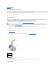
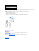
Back to Contents Page Battery Dell Precision™ WorkStation 340 Service Manual The 3.0-V CR2032 coin-cell battery installed on the system board provides power to retain the configuration, date, and time information when the computer is turned off. The computer battery is designed to provide years of service without being replaced.
1 battery 2 battery socket 6. Close the computer cover. 7. Reconnect the computer and devices to their electrical outlets, and turn them on. NOTE: If enabled, the Chassis Intrusion option will cause the following message to be displayed at the next computer start-up: ALERT! Cover was previously removed. 8. Enter system setup and enter the current time and date. Then exit system setup and save the information. For more information on entering system setup, see your User's Guide. 9.
Back to Contents Page Chassis Intrusion Switch Dell Precision™ WorkStation 340 Service Manual Removing the Chassis Intrusion Switch CAUTION: Before you perform this procedure, see "Safety First—For You and Your Computer." NOTICE: Before disconnecting a device from the computer or removing a component from the system board, verify that the standby power light on the system board has turned off. To locate this light, see "System Board Components." 1.
Replacing the Chassis Intrusion Switch To replace the chassis intrusion switch, follow the "Removing the Chassis Intrusion Switch" procedures in reverse order. Resetting the Chassis Intrusion Detector 1. Enter system setup by pressing during the computer's POST. For instructions on using system setup, see the User's Guide. 2. Under the System Security tab, reset the Chassis Intrusion option by pressing the left- or right-arrow key to select Reset.
Back to Contents Page Computer Cover Dell Precision™ WorkStation 340 Service Manual Opening the Computer Cover CAUTION: Before you perform this procedure, see "Safety First—For You and Your Computer." NOTICE: Before disconnecting a device from the computer, wait 10 to 20 seconds after disconnecting the computer from its electrical outlet. Before removing a component from the system board, verify that the standby power light on the system board has turned off.
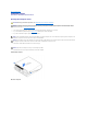
Closing the Computer Cover 1. 2. 3. Check all cable connections, especially those that might have come loose during your work. Fold cables out of the way so that they do not obstruct the computer cover. Ensure that no tools or extra parts (including screws) are left inside the computer. Close the computer cover by pivoting the cover down toward the back of the computer and into position. Make sure that the release buttons click into place. Small Desktop Computer Mini-Tower Computer 4.
Back to Contents Page
Back to Contents Page Control Panel Dell Precision™ WorkStation 340 Service Manual CAUTION: Before you perform this procedure, see the safety instructions in your System Information Guide. NOTICE: To avoid electrostatic discharge, ground yourself by using a wrist grounding strap or by periodically touching an unpainted metal surface (such as the back panel) on the computer.
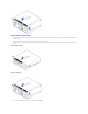
1 computer cover tab (remove the CD drive to access this tab) 2 top-panel tabs 3 top panel 4 bottom panel 5 computer cover screw 6 computer cover tabs (2) 2. To prepare the computer cover for removal, release the three computer cover tabs (one tab is located by the CD drive and two tabs are located by the I/O panel). NOTE: To release the tab located by the CD drive, you can pry the computer cover away from the computer and pull out the tab. 3. If necessary, remove the computer cover screw. 4.
Back to Contents Page Drives Dell Precision™ WorkStation 340 Service Manual NOTE: Cable ends are color coded so that black identifies the floppy-disk drive cable, yellow the front I/O panel cable, orange the secondary IDE cable, white the SCSI cable, and blue the primary IDE cable. CAUTION: To avoid the possibility of electric shock, turn off the computer and any devices, disconnect them from their electrical outlets, and then wait at least 5 seconds before you open the computer cover.
6. If the replacement drive does not have the bracket rails attached, remove the rails from the old drive by removing the two screws that secure each rail to the drive. Drive-Rail Bracket Removal and Replacement 7. Attach the bracket to the new drive by aligning the screw holes on the drive with the screw holes on the rails and tightening all four screws. 8. Reinstall the 3.5-inch floppy drive and bracket assembly by gently sliding the bracket into place until the tabs securely click into position.
1 power cable 4 floppy-drive connector 2 floppy cable 5 power connector 3 floppy-cable connector Removing and Installing a Floppy Drive—Mini-Tower Computer 1. Unpack the drive and prepare it for installation. Check the documentation that accompanied the drive to verify that the drive is configured for your computer. Change any settings necessary for your configuration. 2. Open the computer cover. 3. Disconnect the power cable and the floppy-drive data cable from the drive. 4.
8. Gently slide the drive into place until the tabs securely click into position. 9. Attach the floppy-drive data cable to the back of the floppy drive. 10. Connect the power cable to the power input connector on the drive. 11. Close the computer cover, reconnect your computer and devices to their electrical outlets, and turn them on. Floppy-Drive Cable Attachment 1 floppy-drive cable 3 floppy-drive cable connector 2 power cable 4 floppy-drive connector Removing and Installing a 5.
1 audio cable 5 power cable connector 2 removable media drive data cable 6 removable media drive connector (IDE SEC) 3 power cable 7 audio cable connector 4 data cable connector 5. Press inward on the two tabs on the sides of the drive bay to disengage the drive from the computer. 6. Slide the drive upward and remove it from the computer. Removable Media Drive Removal 7.
10. Reinstall the removable media drive and bracket assembly by gently sliding the bracket into place until the tabs securely click into position. 11. If you are installing a drive that has its own controller card, install the controller card in an expansion slot. NOTE: Problems may arise if two expansion cards are trying to use the same resources: memory, I/O addresses, and IRQs.
16. If the removable media drive bay was previously empty, remove the front-panel insert from the front panel. 17. Close the computer cover, reconnect your computer and devices to their electrical outlets, and turn them on. 18. If necessary, update your configuration information in system setup. 19. Verify that your computer works correctly by running the Dell Diagnostics. For more information on using the Dell Diagnostics, see your User's Guide. Removing and Installing a 5.
NOTE: Problems may arise if two expansion cards are trying to use the same resources: memory, I/O addresses, and IRQs. To avoid this type of conflict, see "Interrupt Assignment Conflicts" in your User's Guide and the documentation that came with the card for more information. 11. Connect the removable media drive power cable and audio cable to the removable media drive. 12. Connect the removable media drive data cable to the removable media drive.
Hard-Drive Shroud and Hard-Drive Removal 5. Disconnect the power and hard-drive data cables from the drive. Hard-Drive Cable Removal 1 hard-drive data cable 2 power cable 3 hard-drive connector (IDE PRI) 6. 7. Remove the drive bracket from inside the computer. a. If a hard drive is already installed in the drive bracket, disconnect the power and hard-drive data cables from the drive. b. Press in on the tabs on each side of the bracket, and slide it up and out.
8. 9. Attach the bracket rails to the new hard drive by aligning the four screw holes of the drive and bracket and then inserting and tightening the screws that came with your upgrade kit. Reinstall the hard-drive bracket by gently sliding the bracket into place until you hear it securely click.
2 power cable 5 hard-drive connector (IDE PRI) 3 power cable connector 11. If it is not already connected, connect the other end of the hard-drive data cable to the IDE PRI connector on the system board. 12. Replace the plastic shroud covering the drive by inserting the two tabs on the bottom into the holes and snapping the top into place. 13. Close the computer cover, reconnect your computer and devices to their electrical outlets, and turn them on. 14.
1 hard-drive data cable 2 power cable 3 hard-drive connector (IDE PRI) 5. 6. Press in on the tabs on each side of the bracket, and slide it up and out. If the replacement drive does not have the bracket rails attached, remove the rails from the old drive by removing the two screws that secure each rail to the drive. NOTICE: To avoid possibly damaging the drive by ESD, ground yourself by touching an unpainted metal surface on the back of the computer.
1 hard-drive data cable 4 hard-drive data cable connector 2 power cable 5 hard-drive connector (IDE PRI) 3 power cable connector 10. Check all connectors to be certain that they are properly cabled and firmly seated. NOTICE: To avoid possible damage to the computer, you must match the colored stripe on the hard-drive data cable with pin 1 on the drive's data cable connector and with the IDE drive data connector (labeled IDE_PRI) on the system board. 11.
Ensure that the rail tabs are positioned at the back of the hard drive. NOTICE: Do not install a drive into the lower hard-drive bay until you remove the green drive rails from inside the hard-drive cage. 5. 6. Remove the first hard drive from the upper bay and install it in the lower bay. a. Disconnect the power cable and the data cable from the back of the first hard drive. b. Press in the two green rail tabs and pull the first hard drive out of the upper bay. c.
1 power cable 2 power input connector The drive's interface connector is a card-edge connector or a header connector, as shown in the following figure. Drive Interface Connectors 1 header connector 2 colored stripe on the cable 3 interface cable When you attach the interface cable to a drive, be sure to match the colored stripe on the cable to pin 1 of the drive's interface connector. For the location of pin 1 on the drive's interface connector, see the documentation that came with the drive.
To transfer data at full speed, Ultra ATA/100 hard drives require an 80-conductor cable like that used with ATA/66 drives. The 80-conductor cable has a 40-pin connector like the ATA/33 cable, but it has twice as many wires within the cable. If you use an ATA/33 cable with Ultra ATA/100 hard drives, the drives will operate properly, but data will transfer at ATA/33 speeds. NOTICE: Dell recommends that you use only IDE cables purchased from Dell.
NOTICE: Dell recommends that you use only SCSI cables purchased from Dell. Cables purchased elsewhere are not guaranteed to work with Dell computers.
Back to Contents Page Protecting Against Electrostatic Discharge Dell Precision™ WorkStation 340 Service Manual Static electricity can harm delicate components inside your computer. To prevent static damage, discharge static electricity from your body before you touch any of your computer's electronic components, such as the microprocessor. You can do so by touching an unpainted metal surface on the computer.
Back to Contents Page Expansion Cards Dell Precision™ WorkStation 340 Service Manual Your computer provides expansion slots for the following cards: l In the small desktop computer, up to two 32-bit, 33-MHz PCI cards. l In the mini-tower computer, up to four 32-bit, 33-MHz PCI cards. l One 32-bit AGP card. The expansion slot supports an AGP 4x (low profile in the small desktop computer) card operating at 1.5 V.
NOTE: See "Expansion Card Cage (Small Desktop Computer Only)" for information on removing the card cage. Mini-Tower Computer Installing an Expansion Card CAUTION: Before you perform this procedure, see "Safety First—For You and Your Computer." NOTICE: Before disconnecting a device from the computer, wait 10 to 20 seconds after disconnecting the computer from its electrical outlet. Before removing a component from the system board, verify that the standby power light on the system board has turned off.
Expansion Card Retention Arm—Mini-Tower Computer 5. If you are installing a new expansion card, remove the filler bracket for an empty card-slot opening. Then continue with step 6. 6. If you are replacing an expansion card that is already installed in the computer, remove the expansion card. If necessary, disconnect any cables connected to the card. Grasp the card by its top corners, and ease it out of its connector. 7. Prepare the new expansion card for installation.
Expansion Card Installation—Mini-Tower Computer 1 card retention arm 2 card connector 3 expansion card 10. Lower the expansion card retention arm and press it into place, securing the expansion card(s) in the computer. 11. Connect any cables that should be attached to the card. See the documentation for the card for information about the card's cable connections. NOTICE: Do not route expansion card cables over or behind the expansion cards.
14. Enter system setup and enable the new expansion card. NOTE: If enabled, the Chassis Intrusion option will cause the following message to be displayed at the next computer start-up: Alert! Cover was previously removed. Reset the chassis intrusion detector. If you installed a sound card, perform the following steps: a. b. Enter system setup, select Integrated Devices (LegacySelect) and change the setting for Sound to Off. Connect external audio devices to the sound card's connectors.
the lever and pull the lever up. AGP Slot Filler Bracket Removal—Small Desktop Computer 1 tab 2 indentation AGP Slot Filler Bracket Removal—Mini-Tower Computer 3. Press the AGP card clip lever toward PCI slot 1. 4. Slide the AGP card into place.
5. Release the AGP card clip lever, ensuring that the tab on the AGP card clip lever fits into the notch on the front end of the AGP card. 6. Secure the AGP card bracket by lowering the securing lever on the back panel. 7. Close the computer cover. Removing an AGP Card 1. Raise the hinged lever on the back on the computer. 2. On the AGP card clip, press the lever toward PCI slot 1. 3. Pull the AGP card up and out of the AGP card clip.
Back to Contents Page Expansion Card Cage (Small Desktop Computer Only) Dell Precision™ WorkStation 340 Service Manual The PCI riser board in the small desktop computer has two PCI expansion card slots. Removing the Expansion-Card Cage CAUTION: Before you perform this procedure, see "Safety First—For You and Your Computer." 1. 2. Open the computer cover. Check any cables connected to expansion cards through the back- panel openings.
Back to Contents Page Front Panel Door and Hinge Arms Dell Precision™ WorkStation 340 Service Manual To prevent damage to your computer, the front door is designed to "break away" if it is lifted up too far. If the front door breaks away, you might need to reattach both the front door and the hinge arms. Reattaching the Front Door 1. Shut down the computer. 2. Lower the hinge arms to the vertical position. 3. Align the two clips on the inside of the front door with the two hinge arms. 4.
1 hinge arms (2) in horizontal position 4. After the hinge arms snap into place, lower and raise the arms two or three times to properly seat them. 5. Reattach the front door (see "Reattaching the Front Door").
Back to Contents Page Front-Panel Inserts Dell Precision™ WorkStation 340 Service Manual Removing Front-Panel Inserts CAUTION: Before you perform this procedure, see "Safety First—For You and Your Computer." 1. 2. 3. Turn off the computer and devices, disconnect them from their electrical outlets, wait at least 10 to 20 seconds, lay the computer on its side, and open the computer cover. On the small desktop computer: a.
Replacing Front-Panel Inserts To replace a front-panel insert, follow the appropriate procedure, in reverse, in "Removing Front-Panel Inserts.
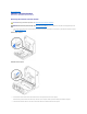
Back to Contents Page Inside Your Computer Dell Precision™ WorkStation 340 Service Manual NOTE: User service access points are color- coded green.
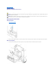
1 removable media drive 8 PCI expansion-card slots (4) 2 floppy drive 9 back panel connectors 3 hard drive 10 AC power connector 4 cover release buttons (2) 11 padlock ring 5 speaker 12 power supply 6 chassis intrusion switch 13 microprocessor airflow shroud 7 system board Back to Contents Page
Back to Contents Page I/O Panel Dell Precision™ WorkStation 340 Service Manual Removing the I/O Panel—Small Desktop Computer CAUTION: Before you perform this procedure, see "Safety First—For You and Your Computer." NOTICE: Before disconnecting a device from the computer or removing a component from the system board, verify that the standby power light on the system board has turned off. To locate this light, see "System Board Components." 1.
1 control-panel cable 2 front audio cable 3 front I/O cable 4 mounting screw 1. 2. Disconnect the control-panel cable from the control-panel connector on the I/O panel. Disconnect the front I/O cable from the front-panel connector on the system board (see "System Board Components" for the location of the front-panel connector). Note the routing of the control panel cable as you remove it from the computer so that you can replace it correctly. 3.
Back to Contents Page Computer Memory Dell Precision™ WorkStation 340 Service Manual Your computer supports dual-channel RDRAM RIMMs in 64-, 128-, 256-, and 512-MB capacities. See "Computer Memory Installation Guidelines" for instructions you must follow when installing memory modules. To locate the memory sockets on the system board, see "System Board Memory Components.
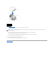
1 RIMM 2 CRIMM NOTICE: If you remove your original memory modules from the computer during a memory upgrade, keep them separate from any new modules that you may have, even if you purchased the new modules from Dell. You must install your original memory modules in pairs either in connectors RIMM1 and RIMM2 or RIMM3 and RIMM4. Do not pair one original memory module with one new memory module. Otherwise, your computer may not start properly. l Memory sockets must be upgraded in matched pairs.
1 securing clips 2 memory module socket Installing a Memory Module 1. If necessary, remove memory modules that occupy system board sockets in which you plan to install upgrade modules. 2. Press the securing clips at each end of the socket outward until they snap open. 3. Align the slots on the bottom of the module with the ridges inside the socket. NOTICE: To avoid damage to the memory module, press the module straight down into the socket with equal force applied at each end of the module. 4.
Back to Contents Page Microprocessor Dell Precision™ WorkStation 340 Service Manual Removing the Microprocessor NOTE: Dell recommends that only a technically knowledgeable person perform this procedure. CAUTION: The processor can get very hot during normal operation. Be sure that the processor has had sufficient time to cool before you touch it. CAUTION: Before you perform this procedure, see "Safety First—For You and Your Computer.
1 securing clips (2) 4 heat sink 2 latches (2) 5 screws (2) 3 retention base 6 blower Heat Sink Removal—Mini-Tower Computer 1 securing clips (2) 4 ZIF socket 2 latches (2) 5 retention base 3 tabs (3) 6 heat sink NOTICE: Gently rock the heat sink and then lift it to remove. 5. Lift the heat sink or heat sink/blower assembly away from the microprocessor. 6. On the small desktop computer, remove the two screws on the blower to remove it from the heat sink.
The ZIF socket has a lever-type handle that secures and releases the microprocessor from the ZIF socket 7. Pull the socket lever up straight up until the microprocessor is released. NOTICE: Be careful not to bend any of the pins when you remove the microprocessor package from the ZIF socket. Bending the package pins can permanently damage the microprocessor. Microprocessor Removal 1 ZIF socket lever 3 microprocessor 2 ZIF socket 8. Remove the microprocessor from the socket.
1 pin-1 corners of microprocessor and the socket NOTICE: The microprocessor pins are delicate. To avoid damage, ensure that the microprocessor aligns properly with the socket, and do not use excessive force when installing the processor. 3. Carefully set the microprocessor in the socket and press it down lightly to seat it. 4. Rotate the lever toward the socket until it snaps into place, securing the microprocessor package.
Back to Contents Page Power Supply Dell Precision™ WorkStation 340 Service Manual Removing the Power Supply CAUTION: Before you perform this procedure, see "Safety First—For You and Your Computer." NOTICE: Before disconnecting a device from the computer, wait 10 to 20 seconds after disconnecting the computer from its electrical outlet. Before removing a component from the system board, verify that the standby power light on the system board has turned off.
2 push button 2. Disconnect the AC power cable from the back of the power supply. 3. Disconnect the DC power cables from the system board and the drives. Note the routing of the DC power cables underneath the clips in the computer as you remove them from the system board and drives. It is important to route these cables properly when you replace them to prevent them from being pinched or crimped. 4.
Back to Contents Page Safety First—For You and Your Computer Dell Precision™ WorkStation 340 Service Manual Use the following safety guidelines to help protect your computer system from potential damage and to ensure your own personal safety. When Working Inside Your Computer Before you open the computer cover, perform the following steps in the sequence indicated. NOTICE: Do not attempt to service the computer yourself, except as explained in your online Dell documentation or otherwise provided to you.
Back to Contents Page System Board Components Dell Precision™ WorkStation 340 Service Manual The following figures show the principal connectors and components on the system board. See "System Board" for information on removing the system board.
1 floppy-drive connector (FLOPPY) 13 PCI riser board 2 battery 14 front-panel audio connector 3 removable-media drive connector (IDE SEC) 15 telephony connector 4 hard-drive connector (IDE PRI) 16 CD audio connector 5 front panel connector 17 back panel connectors 6 system board speaker 18 microprocessor power connector 7 password jumper 19 microprocessor/heat sink assembly 8 auxiliary hard-drive activity light connector 20 memory module sockets (RIMM 1 and 2) 9 CLR CMOS jumper 21 f
PSWD Password jumper RIMM_n Memory module socket SERIALn Serial connectors (2) SCSI Auxiliary hard-drive activity light connector SPEAKER System board speaker STANDBY_LED Standby power light TELE Telephony (TAPI) connector USB_LAN Network and Port 1 USB (2) connectors Jumpers System Board Jumpers NOTICE: Before changing a jumper setting, verify that the standby power light on the system board has turned off. Otherwise, damage to your computer or unpredictable results may occur.
Back to Contents Page System Board Dell Precision™ WorkStation 340 Service Manual Removing the System Board CAUTION: Before you perform this procedure, see "Safety First—For You and Your Computer." NOTICE: Before disconnecting a device from the computer or removing a component from the system board, verify that the standby power light on the system board has turned off. To locate this light, see "System Board Components." 1. Write down your BIOS settings before you turn off your computer.
6. Orient the replacement board by aligning the notches on the bottom to the tabs on the computer floor. 7. Slide the board toward the back of the computer until it clicks into place. 8. Replace any components and cables that you removed from the system board. 9. Reconnect all cables to their connectors at the back of the computer, close the computer cover, and reconnect the computer and devices to their power sources and turn them on.
Back to Contents Page Dell Precision™ WorkStation 340 Service Manual NOTE: A NOTE indicates important information that helps you make better use of your computer. NOTICE: A NOTICE indicates either potential damage to hardware or loss of data and tells you how to avoid the problem. CAUTION: A CAUTION indicates a potential for property damage, personal injury, or death. ____________________ Information in this document is subject to change without notice. © 2003 Dell Computer Corporation.