
User Manual
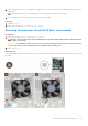
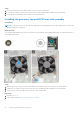
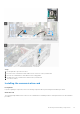
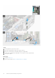
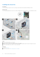
Table Of Contents
- OptiPlex 7000 Tower Service Manual
- Contents
- Working inside your computer
- Removing and installing components
- Recommended tools
- Screw list
- Major components of OptiPlex 7000 Tower
- Side cover
- Front bezel
- Hard-drive assembly
- 3.5 in. hard-drive assembly
- Solid-state drive
- WLAN card
- Coin-cell battery
- Memory module
- Expansion card
- Graphical processing unit
- Slim optical-drive
- Slim optical-drive bracket
- Speaker
- Power-supply unit
- Processor fan and heat-sink assembly
- Processor
- Communication card
- Chassis fan
- Voltage regulator heat sink
- Power button
- Intrusion switch
- SD card reader (optional)
- Optional modules
- Removing optional DisplayPort module
- Installing optional DisplayPort module
- Removing optional VGA module
- Installing optional VGA module
- Removing optional HDMI module
- Installing optional HDMI module
- Removing optional Serial module
- Installing optional Serial module
- Removing optional Type-C module
- Installing optional Type-C module
- Removing optional Thunderbolt 4 module
- Installing optional Thunderbolt4 module
- Removing internal antenna
- Installing internal antenna
- System board
- Drivers and downloads
- BIOS setup
- Troubleshooting
- Getting help and contacting Dell

Steps
1. Insert the processor fan into its slot in the heat-sink.
2. Replace the four screws to secure the processor fan to the heat-sink assembly.
Next steps
1. Install the processor fan and heat-sink assembly.
2. Install the side cover.
3. Follow the procedure in after working inside your computer.
Installing the processor fan and 125 W heat-sink assembly
Prerequisites
If you are replacing a component, remove the existing component before performing the installation procedure.
NOTE: If either the processor or the heat sink is replaced, use the thermal grease that is provided in the kit to ensure that
thermal conductivity is achieved.
About this task
The following image indicates the location of the processor fan and 125 W heat-sink and provides a visual representation of the
installation procedure.
Steps
1. Align the screws on the processor fan and heat-sink assembly with the screw holders on the system board and place the
processor fan and heat-sink assembly on the processor.
NOTE: Ensure that the triangle mark is directed towards the rear side of the computer.
62 Removing and installing components