Dell™ XPS™ 410 Service Manual Before You Begin About Your Computer Technical Overview Specifications Advanced Troubleshooting System Setup Removing and Installing Parts Notes, Notices, and Cautions NOTE: A NOTE indicates important information that helps you make better use of your computer. NOTICE: A NOTICE indicates either potential damage to hardware or loss of data and tells you how to avoid the problem. CAUTION: A CAUTION indicates a potential for property damage, personal injury, or death.
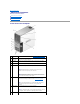
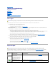
Back to Contents Page About Your Computer Dell™ XPS™ 410 Service Manual Front View of the Computer Back View of the Computer Back Panel Connectors Front View of the Computer 1 cover release latch Use this latch to remove the cover (see Removing the Computer Cover). 2 CD or DVD activity light The CD or DVD drive light is on when the computer reads data from or writes data to the CD or DVD drive. 3 CD or DVD eject button Press the CD or DVD eject button to eject a disc from the CD or DVD drive.
a CD player is operating. 9 diagnostic lights (4) Use the sequence of the diagnostic lights to help you troubleshoot a problem with your computer (see Diagnostic Lights). 10 headphone connector Use the headphone connector to attach headphones and most kinds of speakers. 11 microphone connector Use the microphone connector to attach a personal computer microphone for voice or musical input into a sound or telephony program.
adapter connector on your computer. A click indicates that the network cable has been securely attached. On computers with an additional network connector card, use the connectors on the card and on the back of the computer when setting up multiple network connections (such as a separate intraand extranet). NOTE: It is recommended that you use Category 5 wiring and connectors for your network. If you must use Category 3 wiring, force the network speed to 10 Mbps to ensure reliable operation.
Back to Contents Page Advanced Troubleshooting Dell™ XPS™ 410 Service Manual Power Lights Diagnostic Lights Beep Codes Dell Diagnostics Drivers Resolving Software and Hardware Incompatibilities Power Lights CAUTION: Before you begin any of the procedures in this section, follow the safety instructions in the Product Information Guide.
Memory modules are detected, but a memory failure has occurred. l l A possible graphics card failure has occurred. l l If two or more memory modules are installed, remove the modules (see Removing Memory), then reinstall one module (see Installing Memory) and restart the computer. If the computer starts normally, continue to install additional modules (one at a time) until you have identified a faulty module or reinstalled all modules without error.
3-1-2 Master DMA register failure 3-1-3 Master interrupt mask register failure 3-1-4 Slave interrupt mask register failure 3-2-2 Interrupt vector loading failure 3-2-4 Keyboard Controller Test failure 3-3-1 NVRAM power loss 3-3-2 NVRAM configuration 3-3-4 Video Memory Test failure 3-4-1 Screen initialization failure 3-4-2 Screen retrace failure 3-4-3 Search for video ROM failure 4-2-1 No time tick 4-2-2 Shutdown failure 4-2-3 Gate A20 failure 4-2-4 Unexpected interrupt in protected mode 4-3-3 Timer-chip cou
POST. be replaced. Invalid Boot Diskette The operating system cannot be located on drive A or drive C. Enter the system setup program (see Entering System Setup)and confirm that drive A or drive C is properly identified. Keyboard Error The BIOS has detected a stuck key. Ensure that nothing is resting on the keyboard; if a key appears to be stuck, carefully pry it up. If the problem persists, you may need to replace the keyboard. KB/Interface Error An error occurred with the keyboard connector.
Drivers Identifying Drivers If you experience a problem with any device, identify whether the driver is the source of your problem and, if necessary, update the driver. Windows XP 1. Click the Start button and click Control Panel. 2. Under Pick a Category, click Performance and Maintenance. 3. Click System. 4. In the System Properties window, click the Hardware tab. 5. Click Device Manager. 6.
4. Double-click the type of device for which you are installing the driver. 5. Double-click the name of the device for which you are installing the driver. 6. Click the Driver tab and click Update Driver. 7. Click Install from a list or specific location (Advanced) and click Next. 8. Click Browse and browse to the location to which you previously extracted the driver files. 9. When the name of the appropriate driver appears, click Next. 10. Click Finish and restart your computer.
Back to Contents Page Before You Begin Dell™ XPS™ 410 Service Manual Getting Started Recommended Tools Turning Off Your Computer Before Working Inside Your Computer Getting Started This manual provides procedures for removing and replacing the components in your computer. Unless otherwise noted, each procedure assumes that the following conditions exist: l You have performed the steps in Turning Off Your Computer and Before Working Inside Your Computer in this section.
NOTICE: To disconnect a network cable, first unplug the cable from your computer and then unplug it from the network port or device. 2. Disconnect any telephone or telecommunication lines from the computer. 3. Disconnect your computer and all attached devices from their electrical outlets, and then press the power button to ground the system board. NOTICE: Before touching anything inside your computer, ground yourself by touching an unpainted metal surface, such as the metal at the back of the computer.
Back to Contents Page Removing and Installing Parts Dell™ XPS™ 410 Service Manual Removing the Computer Cover Inside View of Your Computer System Board Components Memory Cards Drive Panels Drives Hard Drive Floppy Drive Media Card Reader CD/DVD Drive Battery Power Supply Processor I/O Panel Processor Fan Card Fan System Board Replacing the Computer Cover This chapter provides procedures for removing and installing the components in your computer.
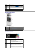
1 cover release latch 2 computer cover 3 hinge tabs (3) 5. Locate the three hinge tabs on the bottom edge of the computer. 6. Grip the sides of the computer cover and pivot the cover up. 7. Lift the cover away and set it aside in a secure location. Inside View of Your Computer CAUTION: Before you perform any of the procedures in this section, follow the safety instructions in the Product Information Guide.
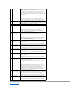
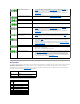
1 memory module connectors (1, 2, 3, 4) 2 battery socket (BATTERY) 3 SATA Connectors SATA0, SATA1 4 front panel I/O connector 5 main power connector 6 SATA connectors (4) (SATA2, SATA3, SATA4, SATA5 7 FlexBay USB connector 8 clear CMOS jumper (CLRCMOS) 9 password jumper (CLRPSWD) 10 PCI Express x1 card connector 11 PCI Express x16 card connector 12 PCI Express x4 card connector 13 PCI card connectors 14 floppy drive connector (FLOPPY) 15 PS/2 and Serial connector 16 card fan connecto
¡ A pair of matched memory modules installed in connectors DIMM_1 and DIMM_2 or ¡ A pair of matched memory modules installed in connectors DIMM_1 and DIMM_2 and another matched pair installed in connectors DIMM_3 and DIMM_4 l If you install mixed pairs of DDR2 533-MHz (PC2-4300), DDR2 667-MHz (PC2-5300), and DDR2 800-MHz (PC2-6400) memory, the modules function at the slowest speed installed.
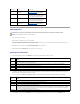
1 memory module connectors (4) 5. 2 securing clip (2) Align the notch on the bottom of the module with the crossbar in the connector. 1 cutouts (2) 4 crossbar 2 memory module 3 notch NOTICE: To avoid damage to the memory module, press the module straight down into the connector while you apply equal force to each end of the module. 6. Insert the module into the connector until the module snaps into position.
10. Click the General tab. 11. To verify that the memory is installed correctly, check the amount of memory (RAM) listed. Removing Memory CAUTION: Before you perform any of the procedures in this section, follow the safety instructions in the Product Information Guide. NOTICE: To prevent static damage to components inside your computer, discharge static electricity from your body before you touch any of your computer's electronic components.
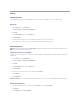
1 release tab 4. 2 card retention mechanism 3 card retention door Push the two release tabs on the card retention door from the inside to pivot the door open; the hinged door will remain in the open position. 1 release tabs (2) 2 filler bracket 4 alignment bar 5 card retention door 3 alignment guide 5. If you are installing a new card, remove the filler bracket to create a card-slot opening. Then continue with step 7. 6.
1 fully seated card 2 not fully seated card 3 bracket within slot 4 bracket caught outside of slot 5 alignment bar 6 alignment guide 9. 1 10. Before you close the card retention door, ensure that: l The tops of all cards and filler brackets are flush with the alignment bar. l The notch in the top of the card or filler bracket fits around the alignment guide. card retention door 2 release tabs (2) Close the card retention door by snapping it into place to secure the cards.
b. 17. Connect the network cable to the add-in network adapter connectors. Do not connect the network cable to the integrated connector on the back panel. Install any drivers required for the card as described in the card documentation. Removing a PCI Card 1. Follow the procedures in Before You Begin. 2. Remove the computer cover (see Removing the Computer Cover). 3. If you are removing the card permanently, install a filler bracket in the empty card-slot opening.
1 card retention door 2 release tabs (2) 3 lever on chassis wall (may not be present on all computers) 4 filler bracket 5 alignment guide 6 alignment bar 2. If present on your computer, rotate the lever on the chassis wall upward. 3. Push the two release tabs on the card retention door from the inside to pivot the door open; the hinged door will remain in the open position.
1 PCI Express x16 card slot 2 PCI Express x16 card 4 PCI Express x1 card 5 PCI Express x1 card slot 7. 3 securing tab Prepare the card for installation. See the documentation that came with the card for information on configuring the card, making internal connections, or otherwise customizing it for your computer. CAUTION: Some network adapters automatically start the computer when they are connected to a network.
b. 15. Connect the network cable to the add-in network adapter's connectors. Do not connect the network cable to the integrated connector on the back panel. Install any drivers required for the card as described in the card documentation. Removing a PCI Express Card 1. Follow the procedures in Before You Begin. 2. Remove the computer cover (see Removing the Computer Cover).
1 PCI Express x16 card slot 2 PCI Express x16 card 4 PCI Express x1 card 5 PCI Express x1 card slot 3 securing tab NOTICE: Ensure that you release the securing tab to unseat the card. If the card is not removed correctly, the system board may be damaged. 6. Release the securing tab on the card slot to unseat the card. 7. If you are removing the card permanently, install a filler bracket in the empty card-slot opening.
1 sliding plate 2 sliding plate lever 3 drive panel 3. Pull the sliding plate lever to the right and hold in place while pushing the panel from the inside. Pivot the panel to the left to release it from its side hinges. 4. Set the drive panel aside in a secure location. Removing the Drive-Panel Insert 1 drive panel 2 drive-panel insert tab 3 drive-panel insert 1.
1 center drive-panel tab 4 drive-panel insert 2 drive panel 3 drive-panel insert tab 1. Slide the tab on the left side of the drive-panel insert under the center drive panel tab. 2. Rotate the drive-panel insert into place and snap the drive-panel insert tab over the corresponding tab on the drive panel. 3. Ensure that the drive-panel insert is correctly seated in the drive panel. Installing the Drive Panel 1. 1 Follow the procedures in Before You Begin.
General Installation Guidelines Connect hard drives to the connectors labeled "SATA0" and "SATA1", starting with SATA0. Connect CD/DVD drives to the connectors labeled "SATA4" and "SATA5", starting with SATA4. Serial ATA hard drives and CD/DVD drives are connected to connectors labeled "SATA0" to "SATA5" on the system board. 1 SATA0 2 SATA1 3 SATA2 4 SATA3 5 SATA4 6 SATA5 When connecting and disconnecting a SATA cable, hold the cable by the connector at each end.
3. 1 Disconnect the power and hard drive cables from the drive. power cable 4. 1 2 hard drive cable Press in on the tabs on each side of the drive and slide the drive up and out. tabs (2) 2 hard drive Installing a Hard Drive 1. Follow the procedures in Before You Begin. 2. Remove the computer cover (see Removing the Computer Cover). 3. Unpack the replacement hard drive, and prepare it for installation. 4.
1 power cable 9. 10. 2 hard drive cable Check all connectors to be certain that they are properly cabled and firmly seated. Replace the computer cover (see Replacing the Computer Cover). NOTICE: To connect a network cable, first plug the cable in to the network wall jack and then plug the cable into the computer. 11. Connect your computer and devices to electrical outlets, and then turn them on.
1 power cable 2 hard drive cable 8. Check all connectors to be certain that they are properly cabled and firmly seated. 9. Replace the computer cover (Replacing the Computer Cover). NOTICE: To connect a network cable, first plug the cable into the network wall jack and then plug it into the computer. 10. Connect your computer and devices to electrical outlets, and then turn them on.
5. Pull the sliding plate to the right and hold in place. 6. Slide the floppy drive out of the floppy drive bay. 1 sliding plate 2 floppy drive Installing a Floppy Drive 1. Follow the procedures in Before You Begin. 2. Remove the computer cover (see Removing the Computer Cover). 3. If you are installing a new floppy drive, remove the shoulder screws from the inside of the drive-panel insert and attach the screws to the new drive. 1 floppy drive 2 shoulder screws (4) 4.
Removing a Media Card Reader CAUTION: Before you perform any of the procedures in this section, follow the safety instructions in the Product Information Guide. NOTICE: To prevent static damage to components inside your computer, discharge static electricity from your body before you touch any of your computer's electronic components. You can do so by touching an unpainted metal surface on the computer chassis. 1. Follow the procedures in Before You Begin. 2.
8. Replace the drive panel (see Installing the Drive Panel). 9. Replace the computer cover (see Replacing the Computer Cover). Installing a Media Card Reader CAUTION: Before you perform any of the procedures in this section, follow the safety instructions in the Product Information Guide. NOTICE: To prevent static damage to components inside your computer, discharge static electricity from your body before you touch any of your computer's electronic components.
9. 10. Route the USB cable through the cable routing clip. Replace the computer cover (see Replacing the Computer Cover). CD/DVD Drive CAUTION: Before you perform any of the procedures in this section, follow the safety instructions in the Product Information Guide. CAUTION: To guard against electrical shock, always unplug your computer from the electrical outlet before opening the cover.
1. Follow the procedures in Before You Begin. 2. Remove the computer cover (see Removing the Computer Cover). 3. If you are installing a new drive, unpack the drive and prepare it for installation. Check the documentation that accompanied the drive to verify that the drive is configured for your computer. 4. 1 If you are installing a new drive, remove the drive panel insert (see Removing the Drive-Panel Insert).
Replacing the Battery CAUTION: Before you perform any of the procedures in this section, follow the safety instructions in the Product Information Guide. NOTICE: To prevent static damage to components inside your computer, discharge static electricity from your body before you touch any of your computer's electronic components. You can do so by touching an unpainted metal surface on the computer. A coin-cell battery maintains computer configuration, date, and time information.
Removing the Power Supply 1. Follow the procedures in Before You Begin. 2. Remove the computer cover (see Removing the Computer Cover). 3. Disconnect the DC power cables from the system board and the drives. NOTE: Note the routing of the DC power cables underneath the tabs in the computer frame as you remove them from the system board and drives. You must route these cables properly when you replace them to prevent them from being pinched or crimped. 4.
7. Connect your computer and devices to electrical outlets, and turn them on. Processor CAUTION: Before you begin any of the procedures in this section, follow the safety instructions in the Product Information Guide. NOTICE: To prevent static damage to components inside your computer, discharge static electricity from your body before you touch any of your computer's electronic components. You can do so by touching an unpainted metal surface on the computer. Removing the Processor 1.
1 heat sink and fan shroud assembly 2 captive screw housing (2) NOTICE: If you are installing a processor upgrade kit from Dell, discard the original heat sink. If you are not installing a processor upgrade kit from Dell, reuse the original heat sink when you install your new processor. 7. Place your finger upon the hook end of the release lever, then push down and out to release it from the tab that secures it 1 processor cover 4 release lever 8.
1 processor cover 2 securing tab 3 processor 4 processor socket 5 center cover latch 6 release lever 7 front alignment notch 8 socket and processor pin-1 indicator 9 rear alignment notch NOTICE: To avoid damage, ensure that the processor aligns properly with the socket, and do not use excessive force when you install the processor. 5. Set the processor lightly in the socket and ensure that the processor is positioned correctly. 6.
10. Replace the computer cover (see Replacing the Computer Cover). NOTICE: To connect a network cable, first plug the cable into the network port or device and then plug the cable into the computer. 11. Connect your computer and devices to electrical outlets, and turn them on. I/O Panel CAUTION: Before you begin any of the procedures in this section, follow the safety instructions in the Product Information Guide.
1 release tab 4 heat sink captive screws (2) 5. 2 card retention mechanism 3 card retention door Use a long Phillips screwdriver to loosen the two captive screws, one on each side of the heat-sink assembly. CAUTION: The heat-sink assembly may be very hot during normal operation. Be sure that it has had sufficient time to cool before you touch it. 6. 1 Rotate the heat-sink assembly towards the rear of the computer, and remove it from the computer.
1 fan release lever 2 fan 3 drive panel 10. Lift the fan release lever, then slide the fan toward the back of the computer to release the four fan tabs from the four slots in the bottom cover. 11. Remove the fan from the computer. 12. Disconnect the control-panel cable from the I/O panel connector by pulling with the cable loop. 13. If present, disconnect the thermal sensor cable (twisted pair) from the I/O panel. 14. Remove the drive panel (see Removing the Drive Panel). 15.
Follow the removal procedure (Removing the I/O Panel) in reverse order, ensuring that the tabs on the top panel, bottom panel, and front panel are secure. Processor Fan CAUTION: Before you begin any of the procedures in this section, follow the safety instructions in the Product Information Guide. CAUTION: To guard against electrical shock, always unplug your computer from the electrical outlet before opening the cover.
1 heat sink and fan shroud assembly 2 captive screw housing (2) 7. Place the heat-sink assembly on its side in a safe place. 8. Disconnect the system fan cable from the system board. 9. Ensure that all cables have been removed from the routing clips on the top of the system fan assembly. 1 fan release lever 4 card fan 2 fan release lever tab 3 processor fan 10.
Removing the Card Fan 1. Follow the procedures in Before You Begin. 2. Remove the computer cover (see Removing the Computer Cover). 3. Disconnect the card fan cable from the system board. 4. Remove any cables from the routing clips on the top of the card fan assembly. 1 fan release lever 4 card fan 2 fan release lever tab 3 processor fan 5.
3. Disconnect any telephone or telecommunication lines from the computer. 4. Disconnect your computer and all attached devices from their electrical outlets, and then press the power button to ground the system board. 5. Open the computer cover (see Removing the Computer Cover). 6. Remove any components that restrict access to the system board (CD/DVD drive(s), floppy drive, hard drive, I/O panel). 7. Remove the heat-sink assembly and processor. 8. Disconnect all cables from the system board. 9.
2. Ensure that no tools or extra parts are left inside the computer. 3. Lower the cover into place: 4. a. Pivot the cover down. b. Press down on the right side of the cover until it closes. c. Press down on the left side of the cover until it closes. Ensure that both sides of the cover are locked. If not, repeat all of step 3. NOTICE: To connect a network cable, first plug the cable into the network wall jack and then plug it into the computer. 5.
Back to Contents Page Specifications Dell™ XPS™ 410 Service Manual Processor Processor type Intel® Pentium® 4 Intel® Pentium® D Intel® Core™ 2 Duo Level 2 (L2) Cache at least 2 MB on Intel Pentium D, Pentium 4, and Core processors Memory Type dual-channel 533-, 667-, and 800-MHz DDR2 Memory connectors four Memory capacities 512 MB or 1 GB Maximum memory 4 GB BIOS address F0000h Computer Information Chipset Intel P965 Express Chipset DMA channels eight Interrupt levels 24 BIOS chip (NVR
PCI Express (x1) connector one x1 connector size 36 pins connector data width (maximum) 1 PCI Express lane PCI Express (x4) connector one x4 (x8 connector wired as x4 electrically) connector size 98 pins connector data width (maximum) 4 PCI Express lanes PCI Express (x16) connector one x16 connector size 164 pins connector data width (maximum) 16 PCI Express lanes Drives Externally accessible: two 3.5-inch drive bays (FlexBay) two 5.
orange light — A good connection exists between a 100-Mbps network and the computer. off (no light) — The computer is not detecting a physical connection to the network. Activity light (on integrated network adapter) yellow light — Blinking indicates activity on the network.
Back to Contents Page System Setup Program Dell™ XPS™ 410 Service Manual Overview Entering System Setup System Setup Screens System Setup Options Boot Sequence Clearing Forgotten Passwords Clearing CMOS Settings Flashing the BIOS Overview Use system setup as follows: l To change the system configuration information after you add, change, or remove any hardware in your computer l To set or change a user-selectable option, such as the user password l To read the current amount of memory or set the type
Lists system information such as the computer name, the BIOS version number and date, system tags, and other system-specific information. System Info NOTE: The system name listed in the BIOS may not appear exactly as the name that appears on the computer or in the computer's documentation. CPU Info Lists the processor type, processor bus speed, processor ID, clock speed, L2 cache, and additional features supported by your processor.
NOTE: Changing the acoustics setting does not alter your hard drive image. Security Admin Password This option provides restricted access to the computer's system setup program in the same way that access to the system can be restricted with the System Password option. System Password Displays the current status of the system's password security feature and allows a new system password to be assigned and verified. Password Status This option locks the system password field with the setup password.
l Onboard SATA Hard Drive — The computer attempts to boot from the primary hard drive. If no operating system is on the drive, the computer attempts to boot from the next bootable device. l Onboard or USB CD-ROM Drive — The computer attempts to boot from the CD drive. If no CD is in the drive, or if the CD has no operating system, the computer attempts to boot from the next bootable device. l USB Device — Insert the memory device into a USB port and restart the computer.
2. Locate the 2-pin password jumper (CLRPSWD) on the system board (see System Board Components), and remove the jumper to clear the password. NOTE: When you receive your computer, the jumper plug is attached to pins 1 and 2. 3. Replace the computer cover (see Replacing the Computer Cover). 4. Connect your computer and monitor to electrical outlets, and then turn them on. 5. After the Microsoft® Windows® desktop appears on your computer, shut down the computer (see Turning Off Your Computer). 6.
Flashing the BIOS The BIOS may require a new flash when an update is available or when replacing the system board. 1. Turn on the computer. 2. Locate the BIOS update file for your computer at support.dell.com. 3. Click Download Now to download the file. 4. If the Export Compliance Disclaimer window appears, click Yes, I Accept the Agreement. The FIle Download window appears. 5. Click Save this program to disk and then click OK. The Save In window appears. 6.
Back to Contents Page Technical Overview Dell™ XPS™ 410 Service Manual Inside View of Your Computer System Board Components Power Supply DC Connector Pin Assignments Inside View of Your Computer CAUTION: Before you use this information in any of the procedures, follow the safety instructions in the Product Information Guide.
1 memory module connectors (1, 2, 3, 4) 2 battery socket (BATTERY) 3 SATA Connectors SATA0, SATA1 4 front panel I/O connector 5 main power connector 6 SATA connectors (4) (SATA2, SATA3, SATA4, SATA5 7 FlexBay USB connector 8 clear CMOS jumper (CLRCMOS) 9 password jumper (CLRPSWD) 10 PCI Express x1 card connector 11 PCI Express x16 card connector 12 PCI Express x4 card connector 13 PCI card connectors 14 floppy drive connector (FLOPPY) 15 PS/2 and Serial connector 16 rear fan connecto
DC Power Connector P1 Pin Number Signal Name Color Wire Gauge 1 +3.3 VDC Orange 18-AWG 2 +3.3 VDC Orange 18-AWG 3 COM Black 18-AWG 4 +5 VDC Red 18-AWG 5 COM Black 18-AWG 6 +5 VDC Red 18-AWG 7 COM Black 18-AWG 8 POK Gray 18-AWG 9 +5 VFP Purple 18-AWG 10 +12 VB DC White 18-AWG 11 +12VB DC White 18-AWG 12 +3.3 VDC Orange 18-AWG 13 +3.
DC Power Connector P2 Pin Number Signal Name 18-AWG Wire 1 COM Black 2 COM Black 3 +12 VA DC Yellow 4 +12 VA DC Yellow DC Power Connect P4 Pin Number Signal Name 18-AWG Wire 1 N/C N/C 2 COM Black 3 COM Black 4 +3.3 VDC Orange 5 +5 VDC Red 6 +12A VDC Yellow DC Power Connect P3, P5, P8, P9, P13, and P14 Pin Number Signal Name 18-AWG Wire 1 +3.
Pin Number Signal Name 18-AWG Wire 1 +5 VDC Red 2 COM Black 3 COM Black 4 +12 A VDC Yellow DC Power Connectors P10 Pin Number Signal Name 18-AWG Wire 1 +12 VA DC Yellow 2 COM Black 3 COM Black 4 +5V DC Red NOTE: The P10 connector is intended for use with PCI Express graphics cards that have power requirements exceeding 75 watts.