Dell™ Dimension™ 4600 Series Service Manual Before You Begin Removing the Computer Cover Technical Overview Technical Specifications Advanced Troubleshooting System Setup Removing and Installing Parts Replacing the Computer Cover Notes, Notices, and Cautions NOTE: A NOTE indicates important information that helps you make better use of your computer. NOTICE: A NOTICE indicates either potential damage to hardware or loss of data and tells you how to avoid the problem.
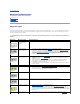
Back to Contents Page Advanced Troubleshooting Dell™ Dimension™ 4600 Series Service Manual Diagnostic Lights Beep Codes System Messages Diagnostic Lights To help you troubleshoot a problem, your computer is equipped with four lights on the back panel labeled "A," "B," "C," and "D." These lights can be yellow or green. When the computer starts normally, the lights flash. After the computer starts, the lights remain green.
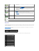
configuration or compatibility error exists. A possible expansion card failure has occurred. l 1. 2. 3. 4. Other failure has occurred. l l l l The computer is in a normal operating condition after POST. If the problem persists, see "Contacting Dell" in your Owner's Manual for instructions on obtaining technical assistance. Determine if a conflict exists by removing a card and then restarting the computer.
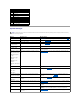
3-4-1 Screen initialization failure 3-4-2 Screen retrace failure 3-4-3 Search for video ROM failure 4-2-1 No time tick 4-2-2 Shutdown failure 4-2-3 Gate A20 failure 4-2-4 Unexpected interrupt in protected mode 4-3-3 Timer-chip counter 2 failure 4-3-4 Time-of-day clock stopped 4-4-1 Serial or parallel port test failure 4-4-4 Cache test failure System Messages NOTE: If the message you received is not listed in the table, see the documentation for either the operating system or the progra
Back to Contents Page
Back to Contents Page Before You Begin Dell™ Dimension™ 4600 Series Service Manual Getting Started Recommended Tools Shutting Down Your Computer Getting Started This section provides procedures for removing and installing the components in your computer. Unless otherwise noted, each procedure assumes that the following conditions exist: l You have performed the steps in "Shutting Down Your Computer." l You have read the safety information in your Owner's Manual.
CAUTION: To guard against electrical shock, always unplug your computer from the electrical outlet before removing the cover. 5. Remove the computer cover. NOTICE: Before touching anything inside your computer, ground yourself by touching an unpainted metal surface, such as the metal at the back of the computer. While you work, periodically touch an unpainted metal surface to dissipate any static electricity that could harm internal components.
Back to Contents Page Replacing the Computer Cover Dell™ Dimension™ 4600 Series Service Manual 1. Ensure that all cables are connected, and fold cables out of the way. 2. Ensure that no tools or extra parts are left inside the computer. 3. Place the cover on the computer. 4. Slide the cover towards the front of the computer until it fits completely into place. NOTICE: To connect a network cable, first plug the cable into the network wall jack and then plug it into the computer. 5.
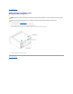
Back to Contents Page Removing the Computer Cover Dell™ Dimension™ 4600 Series Service Manual CAUTION: Before you begin any of the procedures in this section, follow the safety instructions in your Owner's Manual or Product Information Guide. CAUTION: To guard against electrical shock, always unplug your computer from the electrical outlet before removing the cover. 1. Follow the procedures in "Before You Begin." 2. Lay your computer on its side with the computer cover facing up. 3.
Back to Contents Page Removing and Installing Parts Dell™ Dimension™ 4600 Series Service Manual PCI Cards Microprocessor AGP Card Fan Assembly Memory System Board Front Panel Power Supply Drives Battery PCI Cards CAUTION: Before you begin any of the procedures in this section, follow the safety instructions in your Owner's Manual or Product Information Guide. CAUTION: To guard against electrical shock, always unplug your computer from the electrical outlet before removing the cover. 1.
5. Secure the filler bracket onto the end of the card with the screw you removed in step 3. 6. Connect any cables that should be attached to the card. See the documentation for the card for information about the card's cable connections. NOTICE: Do not route card cables over or behind the cards. Cables routed over the cards can cause damage to the equipment. 7. Replace the computer cover.
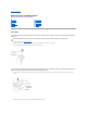
Installing an AGP Card 1. To add or replace the card, press the card lever toward the PCI connector and gently press the card into the AGP connector until it clicks into place. 2. Release the card lever, ensuring that the tab fits into the notch on the front end of the card. 3. Secure the card with the securing screw. 4. If your computer did not previously have an AGP card installed, move the monitor cable to the VGA connector on the new card. 5. Replace the computer cover.
DDR Memory Overview DDR memory modules should be installed in pairs of matched memory size. This means that if you purchased your computer with 128 MB of memory installed and you want to add another 128 MB of memory, you should install it in the appropriate connector. If the DDR memory modules are not installed in matched pairs, the computer will continue to operate, but with a slight reduction in performance. NOTE: Always install DDR memory modules in the order indicated on the system board.
If the module is difficult to remove, gently ease the module back and forth to remove it from the connector. 4. To insert a module, press out the securing clip at each end of the memory module connector. 5. Align the notch on the bottom of the module with the crossbar in the connector. NOTICE: To avoid breaking the memory module, do not press near the middle of the module. 6.
Removing the Front Panel CAUTION: Before you begin any of the procedures in this section, follow the safety instructions in your Owner's Manual or Product Information Guide. CAUTION: To guard against electrical shock, always unplug your computer from the electrical outlet before removing the cover. 1. Follow the procedures in "Before You Begin." 2. Release and remove the front panel: a. Push the release lever to release the top tab. b.
Removing the Front-Panel Insert CAUTION: Before you begin any of the procedures in this section, follow the safety instructions in your Owner's Manual or Product Information Guide. CAUTION: To guard against electrical shock, always unplug your computer from the electrical outlet before removing the cover. 1. Follow the procedures in "Before You Begin." 2. Remove the front panel. 3. Pull the two front-panel tabs towards you, and then push out the front-panel insert.
CAUTION: To guard against electrical shock, always unplug your computer from the electrical outlet before removing the cover. NOTICE: To avoid damage to the drive, do not set it on a hard surface. Instead, set the drive on a soft surface, such as a foam pad, that will sufficiently cushion it. 1. Follow the procedures in "Before You Begin." 2. Remove the hard drive: a. Disconnect the power and hard-drive cables from the drive. b.
NOTICE: Match the colored strip on the cable with pin 1 on the drive (pin 1 is marked as "1"). 6. Connect the power and data cables to the back of the replacement drive. 7. Replace the computer cover. NOTICE: To connect a network cable, first plug the cable into the network wall jack and then plug it into the computer. 8. Connect your computer and devices to electrical outlets, and turn them on. 9.
NOTICE: Ground yourself by touching an unpainted metal surface on the back of the computer. NOTICE: When you unpack the drive, do not set it on a hard surface, which may damage the drive. Instead, set the drive on a soft surface, such as a foam pad, that will sufficiently cushion it. 5. Unpack the additional hard drive. 6. Check the jumper setting on the back of the second drive.
9. 10. Connect the power and data cables to the back of the drives. Replace the computer cover. NOTICE: To connect a network cable, first plug the cable into the network wall jack and then plug it into the computer. 11. Connect your computer and devices to electrical outlets, and turn them on. See the documentation that came with the drive for instructions on installing any software required for drive operation.
forward into position. NOTE: The top of the floppy drive bracket has two slots that fit into two clips on the bottom of the upper drive bay. When the floppy drive bracket is properly mounted, it remains in place without support. 7. Secure the floppy drive bracket with the top bracket screw that came with your drive. 8. Reattach the front panel to the side hinges, and then rotate it until it snaps onto the front of the computer. 9.
NOTE: Drives sold by Dell come with their own operating software and documentation. After you install a drive, see the documentation that came with the drive for instructions on installing and using the drive software. 2. Release and remove the front panel. 3. Pull the two front-panel tabs towards you, and then push out the front-panel insert. 4. Ensure that the jumper setting on the new drive is set for "cable select" (see the documentation that came with the drive for information). 5.
NOTICE: Match the colored strip on the cable with pin 1 on the drive (pin 1 is marked as "1"). 9. Connect the power cable to the system board. 10. Locate the data cable from the CD or DVD drive in the upper drive bay and connect its middle data connector to the new drive. 11. Check all cable connections, and then fold the cables out of the way to provide airflow for the fan and cooling vents. 12.
CAUTION: The heat sink can get very hot during normal operation. Be sure that the heat sink has had sufficient time to cool before you touch it. 5. Remove the microprocessor heat sink: a. Twist the heat sink from side to side to break the seal. a. Remove the retention module clip by pressing in on the tab and lifting the retention module clip up. b. Pull the release tab out until the heat sink is released. c. Lift the heat sink away from the microprocessor.
Installing the Microprocessor NOTICE: Ground yourself by touching an unpainted metal surface on the back of the computer. NOTICE: Be careful not to bend any of the pins when you unpack the microprocessor. Bending the pins can permanently damage the microprocessor. If any of the pins on the microprocessor appears to be bent, see "Contacting Dell" in your Owner's Manual for instructions on obtaining technical assistance. 1. Unpack the new microprocessor.
b. Lower the heat sink until it fits securely in the module. c. When the heat sink is secured, pivot the retention module clip down until the tab snaps into place to secure the heat sink. 7. Lower the airflow shroud over the heat sink. 8. Reconnect the cooling fan power cable to the fan connector (J1F1) on the system board. 9. Reconnect the power cable to the microprocessor power connector (J5B1) on the system board. 10. Replace the computer cover.
6. Remove the fan assembly from the computer. Replacing the Fan Assembly 1. Align the fan assembly tabs with the holes in the back of the computer. 2. Slide the fan assembly away from the fan release lever until it clicks in place. 3. Reconnect the DC power cables to the drives and system board. 4. Replace the computer cover. 5. Connect the AC power cable to the AC power connector on the back of the power supply.
9. 10. Lift the system board out from the computer. Place the system board that you just removed next to the replacement system board. Visually compare the replacement system board to the existing system board to ensure that you have the correct part. Installing the System Board 1. Transfer components from the existing system board to the replacement system board: a. Remove the memory modules and install them on the replacement board. CAUTION: The microprocessor package can get hot.
CAUTION: Before you begin any of the procedures in this section, follow the safety instructions in your Owner's Manual or Product Information Guide. CAUTION: To guard against electrical shock, always unplug your computer from the electrical outlet before removing the cover. 1. Follow the procedures in "Before You Begin." 2. Remove the fan assembly. 3. Disconnect the AC power cable from the AC power connector on the back of the power supply. 4.
If you have to repeatedly reset time and date information after turning on the computer, replace the battery. CAUTION: A new battery can explode if it is incorrectly installed. Replace the 3-V CR2032 battery only with the same or equivalent type recommended by the manufacturer. Discard used batteries according to the manufacturer's instructions. Replacing the Battery 1. Record all the screens in system setup so that you can restore the correct settings when you perform step 8. 2.
Back to Contents Page Technical Specifications Dell™ Dimension™ 4600 Series Service Manual Microprocessor Audio System Information Network Expansion Bus Controls and Lights Memory Power Drives Physical Ports and Connectors Environmental Video Microprocessor Microprocessor type Level 1 (L1) cache Level 2 (L2) cache Intel® Pentium® 4 that runs at 2.26, 2.4, 2.533, 2.66, 2.8, or 3.06 GHz internally and 533 MHz externally, or 2.4, 2.6, 2.8, 3.0, 3.2, or 3.
Ports and Connectors Externally accessible: Serial 9-pin connector; 16550Ccompatible Parallel 25-hole connector (bidirectional) Video 15-hole connector Keyboard 6-pin mini-DIN connector Mouse 6-pin mini-DIN connector USB Network two front-panel and six back-panel USB 2.
Environmental Temperature: Operating 10º to 35ºC (50º to 95ºF) NOTE: At 35°C (95°F), the maximum operating altitude is 914 m (3000 ft). Storage Relative humidity –40º to 65ºC (–40º to 149ºF) 20% to 80% (noncondensing) Maximum vibration: Operating 0.25 G at 3 to 200 Hz Storage 2.20 Grms at 10 to 500 Hz Maximum shock: Nonoperating (half-sine pulse) Nonoperating (faired-square wave) 105 G, 2 ms 32 G with a velocity change of 596.9 cm/sec (235 inches/sec) Altitude: Operating –15.
Back to Contents Page System Setup Dell™ Dimension™ 4600 Series Service Manual Overview Entering System Setup Clearing Forgotten Passwords Overview Use system setup as follows: l To change the system configuration information after you add, change, or remove any hardware in your computer l To set or change a user-selectable option such as the user password l To read the current amount of memory or set the type of hard drive installed Before you use system setup, you must know the kind of floppy dri
or Scrolls through help information. Enters the selected field's pop-up options menu. spacebar, <=> or <-> In the selected field's pop-up options menu, cycles through the options in a field. Exits system setup without restarting the computer and returns the computer to the boot routine. Exits system setup and restarts the computer, implementing any changes you have made. Resets the selected option to the default setting.
System Memory Channel Mode Displays the mode of your system memory. AGP Aperture Displays the amount of aperture memory. The default setting is 128 MB. CPU Information CPU Speed The processor speed at which the computer boots. Press the left- or right-arrow key to toggle the CPU Speed option between the resident processor's rated speed (the default speed) and a lower-compatibility speed. A change to this option takes effect immediately and no restart is necessary.
Suspend Mode The options are S1 or S3. AC Power Recovery Determines what happens when AC power is restored to the computer. l l l Low Power Mode Off (default) — The computer remains off when AC power is restored. On — The computer starts when AC power is restored. Last — The computer returns to the AC power state existing at the time that AC power was lost. The settings are Enabled and Disabled. See "Power Problems" in your Owner's Manual for more information.
Option Settings l Normal — (Available only for the current boot process) The computer attempts to boot from the sequence of devices specified in system setup. l Diskette Drive — The computer attempts to boot from the floppy drive. If the floppy disk in the drive is not bootable, or if no floppy disk is in the drive, the computer generates an error message. l Hard Drive — The computer attempts to boot from the primary hard drive.
6. Turn off the monitor and disconnect it from the electrical outlet. 7. Disconnect the computer power cable from the electrical outlet, and press the power button to ground the system board. 8. Remove the computer cover. 9. Locate the 3-pin password jumper (CLR PASSWRD) on the system board and attach the jumper to pins 1 and 2 to reenable the password feature. 10. Replace the computer cover.
Back to Contents Page Technical Overview Dell™ Dimension™ 4600 Series Service Manual Inside View of Your Computer System Board Components Power Supply DC Connector Pin Assignments Inside View of Your Computer CAUTION: Before you begin any of the procedures in this section, follow the safety instructions in your Owner's Manual or Product Information Guide. CAUTION: To guard against electrical shock, always unplug your computer from the electrical outlet before removing the computer cover.
Power Supply DC Connector Pin Assignments The 250-W power supply can operate from an AC power source of 115 VAC at 60 Hz or 230 VAC at 50 Hz. The power supply provides the DC operating voltages and currents listed in the following table.
+12 VDC 0.0 14.03 +5 VDC 1.0 22.03 +3.3 VDC 0.1/0.02 18.03 –12 VDC 0.0 1.0 +5 VFP 0.0 2.0 When the current load is outside of the ranges listed, but within each specified output current range, the +5-V, +12-V, and +3.3-V outputs are allowed to regulate at +/–10% of nominal DC voltages. 1 Maximum continuous total DC output cannot exceed 200 W. Maximum continuous combined load on +5-VDC and +3.3-VDC outputs cannot exceed 135 W. 2 In system applications where +3.
3 +12 VDC Yellow 4 +12 VDC Yellow DC Power Connectors P3, P5, P6, P8 and P9 Pin Number Signal Name 18-AWG Wire 1 +12 VDC Yellow 2 COM Black 3 COM Black 4 +5 VDC Red DC Power Connector P4 Pin Number Signal Name 22-AWG Wire 1 - No connect 2 COM Black 3 COM Black 4 +3.
Back to Contents Page Dell™ Dimension™ 4600 Series Service Manual NOTE: A NOTE indicates important information that helps you make better use of your computer. NOTICE: A NOTICE indicates either potential damage to hardware or loss of data and tells you how to avoid the problem. CAUTION: A CAUTION indicates a potential for property damage, personal injury, or death. For a complete list of abbreviations and acronyms, see the Tell Me How help file.