Dell OptiPlex 9010/7010 Desktop Owner's Manual Regulatory Model: D05D Regulatory Type: D05D002
Notes, Cautions, and Warnings NOTE: A NOTE indicates important information that helps you make better use of your computer. CAUTION: A CAUTION indicates either potential damage to hardware or loss of data and tells you how to avoid the problem. WARNING: A WARNING indicates a potential for property damage, personal injury, or death. Copyright © 2015 Dell Inc. All rights reserved. This product is protected by U.S. and international copyright and intellectual property laws.
Contents 1 Working on Your Computer....................................................................................................... 5 Before Working Inside Your Computer.....................................................................................................................5 Turning Off Your Computer....................................................................................................................................... 6 After Working Inside Your Computer....................
Removing The Power Switch..................................................................................................................................32 Installing The Power Switch...................................................................................................................................34 Removing The Input/Output Panel.......................................................................................................................... 34 Installing The Input/Output Panel...
Working on Your Computer 1 Before Working Inside Your Computer Use the following safety guidelines to help protect your computer from potential damage and to help to ensure your personal safety. Unless otherwise noted, each procedure included in this document assumes that the following conditions exist: • You have read the safety information that shipped with your computer. • A component can be replaced or--if purchased separately--installed by performing the removal procedure in reverse order.
. Remove the cover. CAUTION: Before touching anything inside your computer, ground yourself by touching an unpainted metal surface, such as the metal at the back of the computer. While you work, periodically touch an unpainted metal surface to dissipate static electricity, which could harm internal components. Turning Off Your Computer CAUTION: To avoid losing data, save and close all open files and exit all open programs before you turn off your computer. 1.
5. If required, verify that the computer works correctly by running the Dell Diagnostics.
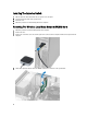
Removing and Installing Components This section provides detailed information on how to remove or install the components from your computer. Recommended Tools The procedures in this document may require the following tools: • Small flat-blade screwdriver • Phillips screwdriver • Small plastic scribe Removing The Cover 1. Follow the procedures in Before Working Inside Your Computer. 2. Pull up the cover release latch, and lift the cover upwards to remove it from the computer.
Removing The Intrusion Switch 1. Follow the procedures in Before Working Inside Your Computer. 2. Remove the cover. 3. Press the clip inwards to release and gently pull the intrusion cable from system board. 4. Slide the intrusion switch outward and remove it from the chassis.
Installing The Intrusion Switch 1. Slide the intrusion switch toward the chassis top and secure it to place. 2. Connect the intrusion cable to the system board. 3. Install the cover. 4. Follow the procedures in After Working Inside Your Computer . Removing The Wireless Local Area Network (WLAN) Card 1. Follow the procedures in Before Working Inside Your Computer. 2. Remove the cover. 3. Remove the screws that secure the antenna puck to the connector on the computer.
Installing The WLAN Card 1. Insert the WLAN card into the connector on the system board and press down until it is securely in place. Fix the latch. 2. Place the antenna puck on the connector and tighten the screws that secure it to the computer. 3. Install the cover. 4. Follow the procedures in After Working Inside Your Computer. Removing The Front Bezel 1. Follow the procedures in Before Working Inside Your Computer. 2. Remove the cover. 3.
Installing The Front Bezel 1. Insert the hooks along the bottom edge of the front panel into the slots on the chassis. 2. Rotate the bezel toward the computer to engage the four front panel retention clips until they click into place. 3. Install the cover. 4. Follow the procedures in After Working Inside Your Computer. Removing The Expansion Card 1. Follow the procedures in Before Working Inside Your Computer. 2. Remove the cover. 3. Lift the release tab on the card-retention latch upward.
4. Press the release lever away from the expansion card and ease the card up and out of its connector. Installing The Expansion Card 1. Insert the expansion card into the connector on the system board to secure it in place and press down the card retention latch downward. 2. Install the cover. 3. Follow the procedures in After Working Inside Your Computer.
NOTE: The memory sockets in your computer may be labeled differently depending on the hardware configuration. For example, A1, A2 or 1,2,3. • If the quad-rank memory modules are mixed with single or dual-rank modules, the quad-rank modules must be installed in the sockets with the white release levers. • If memory modules with different speeds are installed, they operate at the speed of the slowest installed memory modules. Removing The Memory 1.
Removing The Coin-Cell Battery 1. Follow the procedures in Before Working Inside Your Computer. 2. Remove the a. cover b. expansion card 3. Carefully press the release latch away from the battery. The battery pops out from the socket, lift the coin-cell battery out of the computer. Installing The Coin-Cell Battery 1. Place the coin cell battery into its slot on the system board. 2. Press the coin cell battery downward until the release latch springs back into place and secures it. 3.
3. Remove the data cable and the power cable from the back of the hard drive. 4. Press the blue securing bracket inward and lift the hard drive bracket out of the bay in an angle.
5. Flex the hard drive bracket and then remove the hard drive from the bracket. 6. Repeat the preceding steps for the second hard drive, if available. Installing The Hard Drive 1. Insert the hard drive into the hard-drive bracket. 2. Press both blue securing-bracket tabs inward and slide the hard drive bracket into the bay in the chassis. 3. Connect the data cable and the power cable to the hard drive. 4. Install the cover. 5. Follow the procedures in After Working Inside Your Computer.
3. Remove the data cable and power cable from the back of the optical drive. 4. Lift up the optical-drive latch and then slide the optical drive towards the front of the computer.
Installing The Optical Drive 1. Push the optical drive from the front towards the back of the computer. 2. Connect the data cable and the power cable to the optical drive. 3. Install the front bezel. 4. Install the cover. 5. Follow the procedures in After Working Inside Your Computer. Removing The Speaker 1. Follow the procedures in Before Working Inside Your Computer. 2. Remove the cover. 3. Disconnect the speaker and unthread it.
4. Press down the speaker-securing tab and slide the speaker upwards to remove it. Installing The Speaker 1. Press the speaker-securing tab and slide the speaker downward to secure it. 2. Thread the speaker cable into the chassis clip. 3. Connect the speaker cable to the system board. 4. Install the cover. 5. Follow the procedures in After Working Inside Your Computer. Removing The Power Supply Unit 1. Follow the procedures in Before Working Inside Your Computer. 2. Remove the a. cover b.
3. Press the plastic clip and disconnect the 4–pin power cable from the system board. 4. Unthread the power cable from the chassis clips.
5. Press and lift the 24–pin cable to disconnect it from the system board. 6. Unthread the 24–pin power cable from the chassis clip.
7. Unthread the power supply cables from the chassis clip. 8. Remove the screws that secure the power supply unit to the back of the computer. 9. Push in on the blue release tab beside the power supply, and slide the power supply towards the front of the computer.
10. Lift the power supply out of the computer. Installing The Power Supply Unit 1. Place the power supply in the chassis and slide towards the back of the system to secure it. 2. Tighten the screws securing the power supply to the back of the computer. 3. Thread the power supply cables into the chassis clips. 4. Connect the 4-pin power cable to the system board. 5. Connect the 24-pin power cable to the system board. 6. Install the optical drive. 7. Install the hard drive. 8.
Removing The Heat Sink 1. Follow the procedures in Before Working Inside Your Computer. 2. Remove the cover. 3. Press the plastic clip and pull the heat-sink cable from the system board. 4. Using a Phillips screwdriver, loosen the captive screws securing the heat-sink assembly to the system board and lift it away from the computer. Lay the assembly with the fan facing downwards, and with the thermal grease facing upwards.
Installing The Heat Sink 1. Place the heat sink into the chassis. 2. Use a Phillips screwdriver to tighten the captive screws securing the heat sink to the system board. 3. Connect the heat sink cable to the system board. 4. Install the cover. 5. Follow the procedures in After Working Inside Your Computer. Removing The Processor 1. Follow the procedures in Before Working Inside Your Computer. 2. Remove the cover. 3. Remove the heat sink. 4.
Installing The Processor 1. Insert the processor into the processor socket. Ensure the processor is properly seated. The golden triangle mark on the processor should align with the triangle mark on the system board. 2. Gently lower the processor cover. 3. Press the release lever down and then move it inward to secure it with the retention hook. 4. Install the heat sink. 5. Install the cover. 6. Follow the procedures in After Working Inside Your Computer. Removing The System Fan 1.
4. Unthread the system-fan cable from the chassis clip. 5. Release the system fan cables from the chassis clip.
6. Press and disconnect the 24–pin power cable from the system board. 7. Unthread the power cables from the chassis clip. 8. Pry and remove the system fan away from the four grommets securing it to the computer.
Installing The System Fan 1. Place the system fan in the chassis. 2. Pass the four grommets through the chassis and slide outward along the groove to secure in place. 3. Thread the system fan connector cables to the chassis clips. 4. Connect the system fan cable to the system board. 5. Thread the power cables to the chassis clips. 6. Connect the 24–pin connector. 7. Install the hard drive. 8. Install the optical drive. 9. Install the front bezel. 10. Install the cover. 11.
3. Disconnect the thermal-sensor cable from the system board. 4. Release the thermal-sensor cable from the chassis clips. 5. Gently press the tabs from both sides to release and remove the thermal sensor away from the chassis.
Installing The Front Thermal Sensor 1. Secure the thermal sensor to the chassis front. 2. Thread the thermal-sensor cable into the chassis clips. 3. Connect the thermal-sensor cable to the system board. 4. Install the hard drive. 5. Install the front bezel. 6. Install the cover. 7. Follow the procedures in After Working Inside Your Computer. Removing The Power Switch 1. Follow the procedures in Before Working Inside Your Computer. 2. Remove the a. cover b. front bezel 3.
4. Press the clips on both sides of the power switch to release it from the chassis and pull the power switch out of the computer. 5. Slide the power-switch cable out through the front of the computer.
Installing The Power Switch 1. Slide the power-switch cable in through the front of the computer. 2. Secure the power-switch cable to the chassis. 3. Connect the power-switch cable to the system board. 4. Install the front bezel. 5. Install the cover. 6. Follow the procedures in After Working Inside Your Computer. Removing The Input/Output Panel 1. Follow the procedures in Before Working Inside Your Computer. 2. Remove the a. cover b. front bezel c. hard drive d. optical drive 3.
4. Unthread and release the power cable and I/O cable from the chassis clip. 5. Press the metal clip and pull upwards to disconnect the USB 3.0 connector. 6. Remove the screw that secures the I/O panel to the computer.
7. Slide the I/O panel towards the left of the computer to release it and pull the I/O panel along with its cable out of the computer. Installing The Input/Output Panel 1. Insert the Input/Output Board into the slot on the chassis front. 2. Slide the Input/Output Board towards the right of the computer to secure to the chassis. 3. Tighten the screw securing the Input/Output Board to the chassis. 4. Thread the Input/Output Board/FlyWire cable into the chassis clip. 5.
4. Remove the screws that secure the system board to the chassis. 5. Slide and remove the system board from the chassis.
System Board Layout The following image displays the system board layout of the computer. 1. PCI Express x16 (wired as x4) connector 2. PCI Card connector 3. PCI Express x1 Card connector 4. Battery socket 5. PCI Express x16 card connector 6. Intruder Connector (Intruder) 7. Fan Connector (Fan_SYS) 8. Power connector (12V_PWRCONN) 9. Processor 10. Fan Connector (Fan_CPU) 11. Memory Module Connectors (DIMM_1-4) 12. Power Switch Connector (PWR_SW) 13.
19. Internal USB Connector (INT_USB) 21. RTC reset jumper (RTCRST) 20. Password Jumper (PSWD) Installing The System Board 1. Align the system board to the port connectors and place the system board in the chassis. 2. Tighten the screws securing the system board to the chassis. 3. Connect all the cables to the system board. 4. Install the processor. 5. Install the heat sink. 6. Install the memory. 7. Install the expansion card. 8. Install the front bezel. 9. Install the cover. 10.
System Setup 3 System Setup enables you to manage your computer hardware and specify BIOS‐level options.
Table 1. Navigation Keys Keys Navigation Up arrow Moves to the previous field. Down arrow Moves to the next field. Allows you to select a value in the selected field (if applicable) or follow the link in the field. Spacebar Expands or collapses a drop‐down list, if applicable. Moves to the next focus area. NOTE: For the standard graphics browser only. Moves to the previous page till you view the main screen.
Table 3. System Configuration Option Description Integrated NIC Allows you to enable or disable the integrated network card. You can set the integrated NIC to: • • • • Disabled Enabled Enabled w/PXE Enabled w/ImageServer NOTE: Depending on the computer and its installed devices, the items listed in this section may or may not appear. Serial Port Allows you to define the serial port settings.
Option Description For Mini-Tower, Desktop, Small Form Factor the options are: • • • • Enable Boot Support Enable Rear Dual USB Ports Enable Rear Quad USB Ports Enable Front USB Ports For Ultra Small Form Factor, the options are: • • • • Enable Boot Support Enable Rear Dual USB 2.0 Ports Enable Rear Dual USB 3.0 Ports Enable Front USB Ports NOTE: USB keyboard and mouse always work in the BIOS setup irrespective of these settings.
Option Description • • • • Password Bypass Admin Password Min Admin Password Max System Password Min System Password Max Allows you to bypass the System Password and the internal HDD password prompts during a system restart. • • Disabled - Always prompt for the system and internal HDD password when they are set. This option is disabled by default. Reboot Bypass - Bypass the password prompts on restarts (warm boots).
Table 5. Secure Boot Option Description Secure Boot Enable Allows you to enable or disable Secure Boot feature • • Expert key Management Disable Enable Allows you to manipulate the security key databases only if the system is in Custom Mode. The Enable Custom Mode option is disabled by default. The options are: • • • • PK KEK db dbx If you enable the Custom Mode, the relevant options for PK, KEK, db, and dbx appear.
Table 7. Power Management Option Description AC Recovery Specifies how the computer will respond when AC power is applied after an AC power loss. You can set the AC Recovery to: • • • Auto On Time Power Off (default) Power On Last Power State This option sets the time of the day when you would like the system to turn on automatically. Time is kept in standard 12-hour format (hour:minutes:seconds). The startup time can be changed by typing the values in the time and A.M./P.M. fields.
Option Description • Block Sleep (S3 state) - This option is disabled by default. Table 8. POST Behavior Option Description Numlock LED Specifies if the NumLock function can be enabled when the system boots. This option is enabled by default. Keyboard Errors Specifies whether keyboard related errors are reported when it boots. This option is enabled by default.
Option Description • DNS (enabled by default) NOTE: This field is only relevant when the Integrated NIC control in the System Configuration group is set to Enabled with ImageServer. ImageServer IP Specifies the primary static IP address of the ImageServer with which the client software communicates. The default IP address is 255.255.255.255.
Updating the BIOS It is recommended to update your BIOS (system setup), on replacing the system board or if an update is available. For laptops, ensure that your computer battery is fully charged and connected to a power outlet 1. Re-start the computer. 2. Go to dell.com/support. 3. Enter the Service Tag or Express Service Code and click Submit. NOTE: To locate the Service Tag, click Where is my Service Tag? NOTE: If you cannot find your Service Tag, click Detect My Product.
Password Type Description Setup password Password that you must enter to access and make changes to the BIOS settings of your computer. CAUTION: The password features provide a basic level of security for the data on your computer. CAUTION: Anyone can access the data stored on your computer if it is not locked and left unattended. NOTE: Your computer is shipped with the system and setup password feature disabled.
3. Select System Password, alter or delete the existing system password and press or . 4. Select Setup Password, alter or delete the existing setup password and press or . NOTE: If you change the System and/or Setup password, re-enter the new password when promoted. If you delete the System and/or Setup password, confirm the deletion when promoted. 5. Press and a message prompts you to save the changes. 6. Press to save the changes and exit from the System Setup.
Diagnostics 4 If you experience a problem with your computer, run the ePSA diagnostics before contacting Dell for technical assistance. The purpose of running diagnostics is to test your computer's hardware without requiring additional equipment or risking data loss. If you are unable to fix the problem yourself, service and support personnel can use the diagnostics results to help you solve the problem.
Troubleshooting Your Computer 5 You can troubleshoot your computer using indicators like Diagnostic Lights, Beep Codes, and Error Messages during the operation of the computer. Power LED Diagnostics The power button LED located on the front of the chassis also functions as a bicolored diagnostic LED. The diagnostic LED is only active and visible during the POST process. Once the operating system starts to load, it is no longer visible.
Amber LED State Description 3,7 some other failure with messages on screen Beep Code The computer can emit a series of beeps during start-up if the display does not show errors or problems. These series of beeps, called beep codes, identify various problems. The delay between each beep is 300 ms, the delay between each set of beeps is 3 sec, and the beep sound lasts 300 ms. After each beep and each set of beeps, the BIOS should detect if the user presses the power button.
Error Message Description Decreasing available memory One or more memory modules may be faulty or improperly seated. Re-install the memory modules and, if necessary, replace them. Diskette drive 0 seek failure A cable may be loose or the computer configuration information may not match the hardware configuration. Diskette read failure The floppy disk may be defective or a cable may be loose. If the drive access light turns on, try a different disk.
Error Message Description Memory double word A memory module may be faulty or improperly seated. Reinstall the memory modules and, if logic failure at necessary, replace them. address, read value expecting value Memory odd/even logic failure at address, read value expecting value A memory module may be faulty or improperly seated.
Error Message Description Time-of-day not setplease run the System Setup program The time or date stored in System Setup does not match the computer clock. Timer chip counter 2 failed A chip on the system board may be malfunctioning. Unexpected interrupt The keyboard controller may be malfunctioning or a memory module may be loose.
6 Specifications NOTE: Offerings may vary by region. For more information regarding the configuration of your computer, click Start (Start icon) → Help and Support, and then select the option to view information about your computer. Table 15. Processor Feature Specification Processor type • • • • • Intel Core i3 series Intel Core i5 series Intel Core i7 series Intel Pentium Dual Core series Intel Celeron series NOTE: Intel Celeron series is only available for the Dell OptiPlex 7010.
Table 17. Video Feature Specification Integrated • • • Discrete Intel HD Graphics (Celero/Pentium CPU-GPU) Intel HD Graphics 2000 (iCore DC/QC Intel 7 Series Express Chipset CPU-GPU combo) Intel HD Graphics 2500/4000 (i3/i5/i7 DC/QC Intel 7 Series Express Chipset CPU-GPU Combo) PCI Express x16 graphics adapter Table 18. Audio Feature Specification Integrated two Channel High Definition Audio Table 19.
Feature Specification Desktop up to one low-profile card Small Form Factor none Ultra Small Form Factor none PCI Express x1: Mini-Tower up to three full-height cards Desktop up to three low-profile cards Small Form Factor up to two low-profile cards Ultra Small Form Factor none PCI-Express x16: Mini-Tower up to two full-height cards Desktop up to two low-profile cards Small Form Factor up to two low-profile cards Ultra Small Form Factor none Mini PCI Express: Mini-Tower none Deskto
Table 24. External Connectors Feature Specification Audio: Front Panel one microphone connector and one headphone connector Back Panel one line-out connector and one line-in/microphone connector Network Adapter one RJ45 connector Serial one 9-pin connector; 16550 C compatible Parallel one 25-pin connector (optional for mini-tower, desktop and small form factor) USB 2.
Feature Specification Mini PCI Express data width (maximum) – one PCI Express lane and one USB interface: Mini-Tower, Desktop, Small Form Factor none Ultra Small Form Factor one 52-pin connector Serial ATA: Mini-Tower four 7-pin connectors Desktop three 7-pin connectors Small Form Factor three 7-pin connectors Ultra Small Form Factor two 7-pin connectors Memory: Mini-Tower, Desktop, Small Form Factor four 240-pin connectors Ultra Small Form Factor two 240-pin connectors Internal USB: Mini-
Table 26. Controls and Lights Feature Specification Front of the computer: Power button light White light — Solid white light indicates power-on state; blinking white light indicates sleep state of the computer. Drive activity light White light — Blinking white light indicates that the computer is reading data from or writing data to the hard drive. Back of the computer: Link integrity light on integrated network adapter Green — a good 10 Mbps connection exists between the network and the computer.
Table 28. Physical Dimension Physical Height Mini-Tower Width Depth Weight 36.00 cm (14.17 inches) 17.50 cm (6.89 inches) 41.70 cm (16.42 inches) 9.40 kg (20.72 lb) Desktop 36.00 cm (14.17 inches) 10.20 cm (4.01 inches) 41.00 cm (16.14 inches) 7.90 kg (17.42 lb) Small Form Factor 29.00 cm (11.42 inches) 9.30 cm (3.66 inches) 31.20 cm (12.28 inches) 6.00 kg (13.22 lb) Ultra Small Form Factor 23.70 cm (9.33 inches) 3.30 kg (7.28 lb) 6.50 cm (2.56 inches) 24.00 cm (9.45 inches) Table 29.
Contacting Dell 7 To contact Dell for sales, technical support, or customer service issues: 1. Visit support.dell.com. 2. Verify your country or region in the Choose a Country/Region drop-down menu at the bottom of the page. 3. Click Contact Us on the left side of the page. 4. Select the appropriate service or support link based on your need. 5. Choose the method of contacting Dell that is convenient for you.